


Homemade 13" Jointer Project
I had sold my old 6" Jet jointer a few years ago, with the intention of replacing it with an 8" helical head Grizzly at some point.
When I saw Matthias Wandel's homemade jointer, I was very intrigued. The idea of being able to build a machine that normally costs upwards of $2500 was very appealing. I didn't want to build a machine that I wouldn't be happy with, and Matthias's machine was not exactly what I was looking for.
One day, while browsing the Sawmill Creek woodworking forum, I came across a member that was selling a 13" Shelix cutterhead from a Delta 22-580 portable planer. For $200, I couldn't pass it up. This purchase was the push I needed to move forward with this project.
I purchased the plans from Matthias, and studied them to see how everything went together. There were several things that I wanted to change, to give me a machine that I would be happy with for a long time. A few of the changes that I wanted to make:
Longer tables. The orginal design was about 48" long, which was about the same as my old 6" Jet. To take advantage of the 13" width, I wanted to increase the length of the tables. I had thought about a 36" infeed and 48" outfeed table, but eventually decised on both tables being 36" long, as I just don't have the room for a 7ft long jointer.
Enclosed base with dust collection. The original plans were for an open base with casters. I wanted to add integral dust collection, and a stable base to enclose the larger motor I was planning on using.
Induction motor. I definitely didn't want to hear a screaming universal motor, so went with a 2HP, TEFC, 3450 rpm motor from Ebay for $200.
Stronger and heavier. I wanted to beef up most areas of the machine, for added strength and longevity. Most notably was the bearing mounts for the cutterhead. While the original plans use plywood to hold the cutterhead bearings, I wanted to use aluminum.
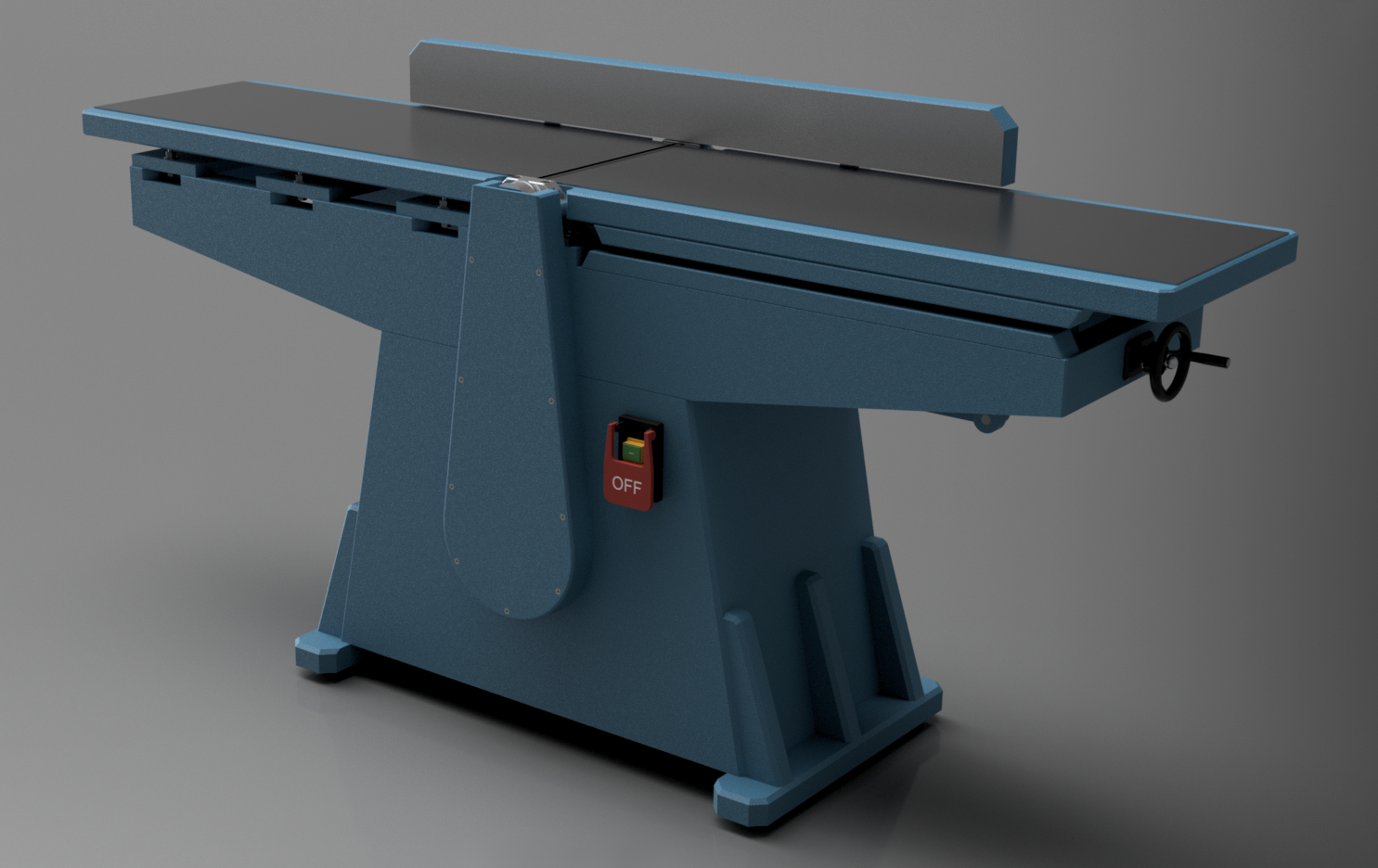
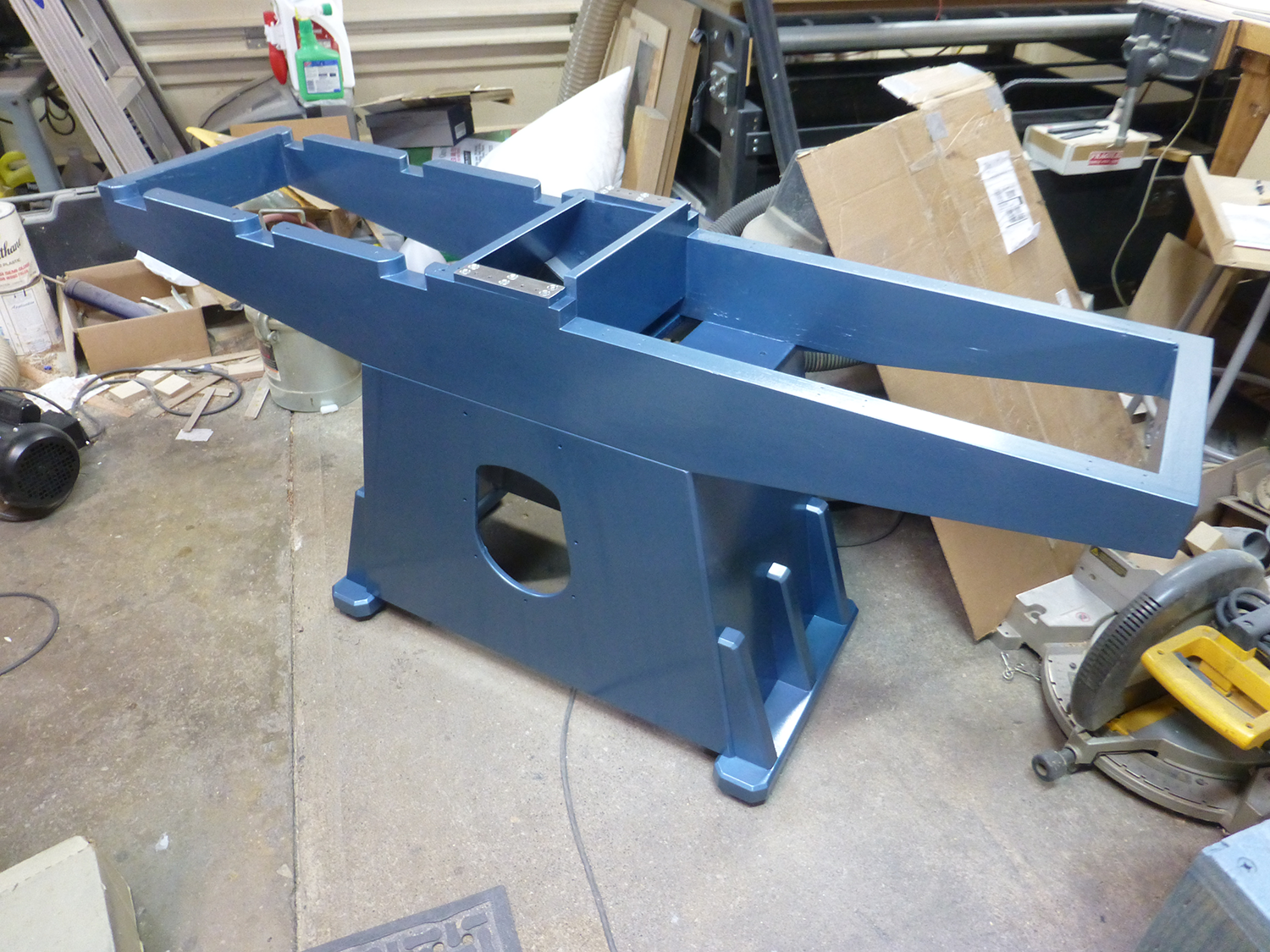
With these objectives, I re-designed almost every part of the machine, using Autodesk's Fusion 360. Below is a rendering of what I came up with. Some minor changes were made during fabrication, but it was built very closely to the Fusion 360 model.
The Frame
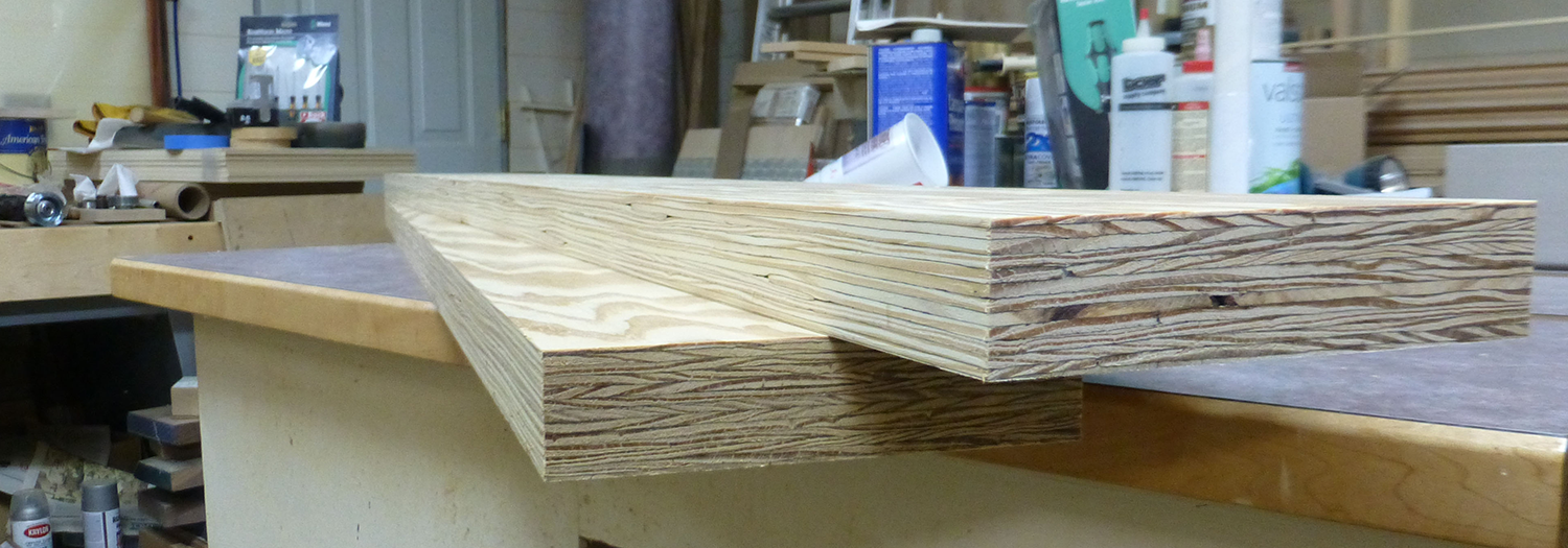
I wanted a sturdy frame to support the larger tables. Rather than using constuction lumber or laminating plywood, I purchased two 1-3/4" x 7-1/4" LVL's. I had never used LVL's before, and was surprised at how "rough" they were. But I ran them through my planer to clean them up, and they cleaned up nicely. But LVL's are very difficult to prep for a high quality finish. If I were to do it over again, I would have made the frame from laminated baltic birch plywood, probably 3 layers of 5/8 or 16mm.
The frame is very simple, consisting of two side pieces, with a crossmember at each end to tie the sides together. The ends were rabbeted to accept the crossmembers, which were then glued and screwed in place. All screw holes were filled with an epoxy-microballons filler.
To cut the angles on the bottom of the frame, I first rough cut them on the bandsaw, then cleaned them up with a flush trimming bit in a router, with a straightedge.
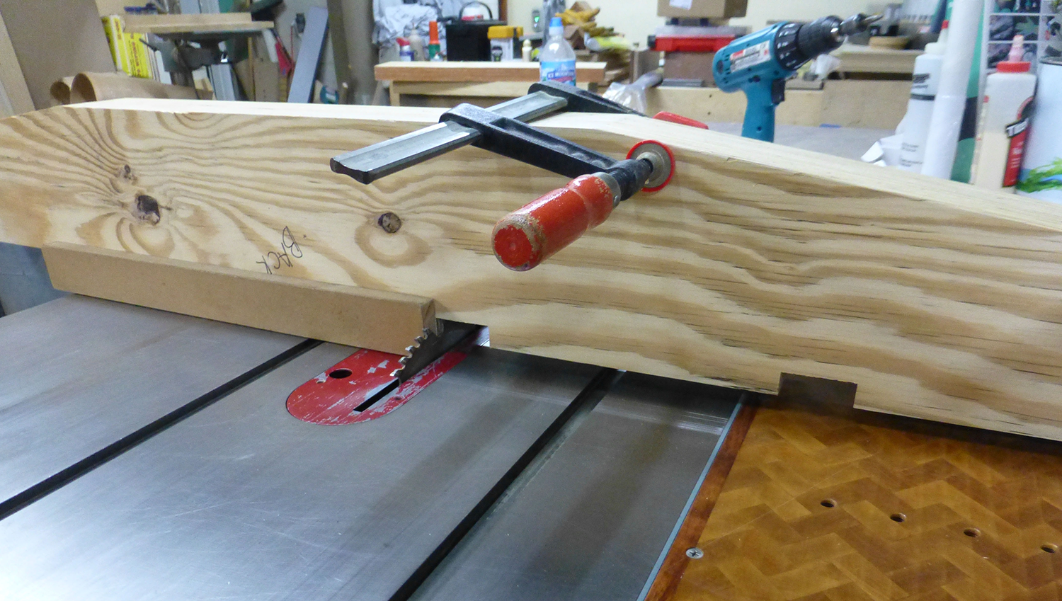
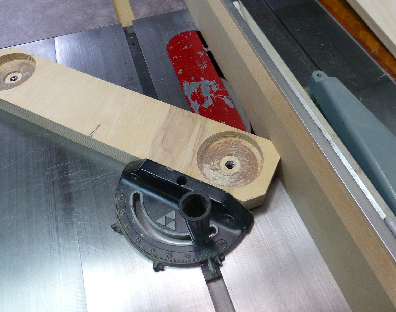
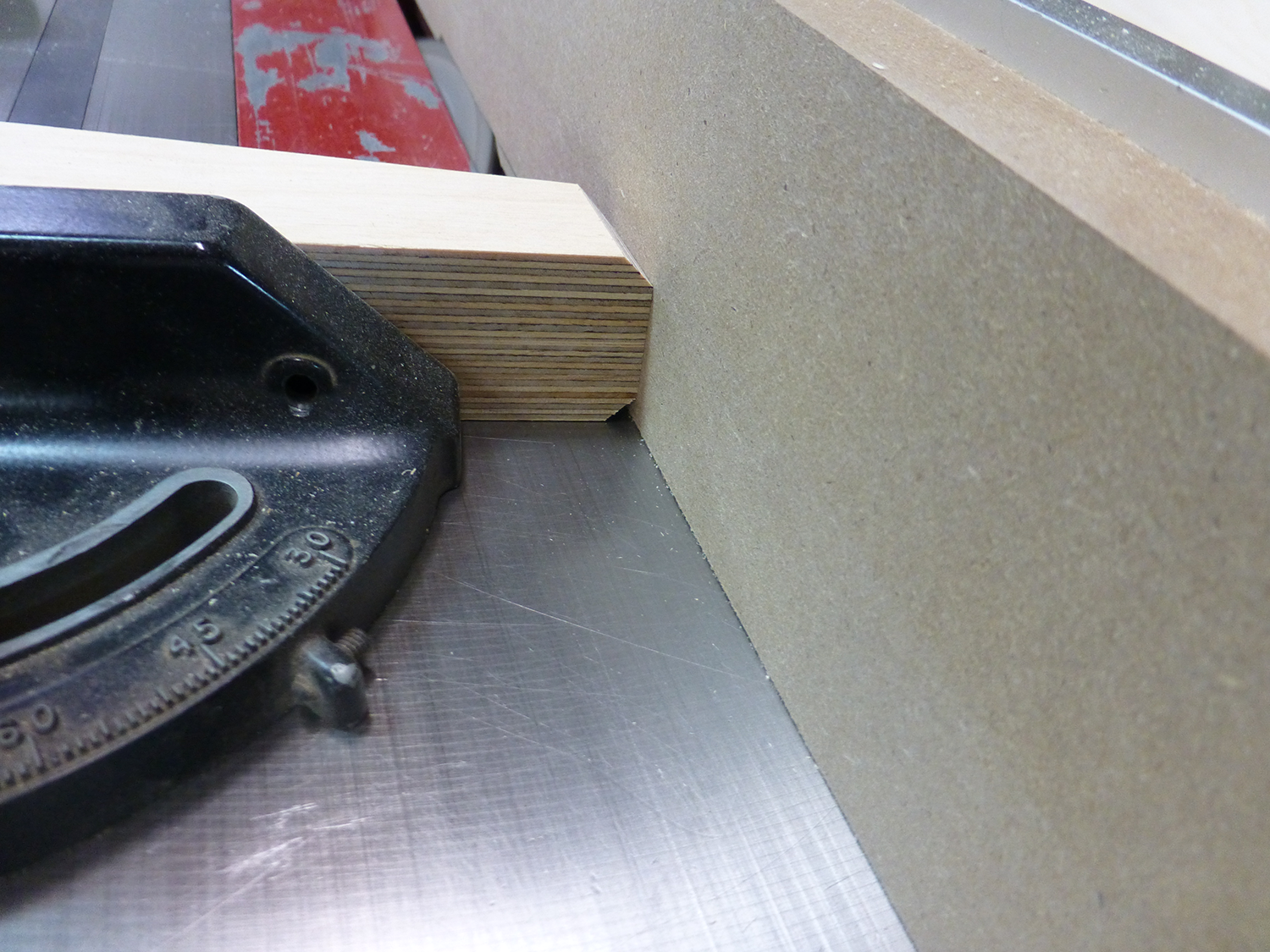
I used a cutoff sled on my table saw to cut the notches on the outfeed side for the table height adjusting screws.
More details of the frame can be seen in some of the other photos show later.
Bearing Supports
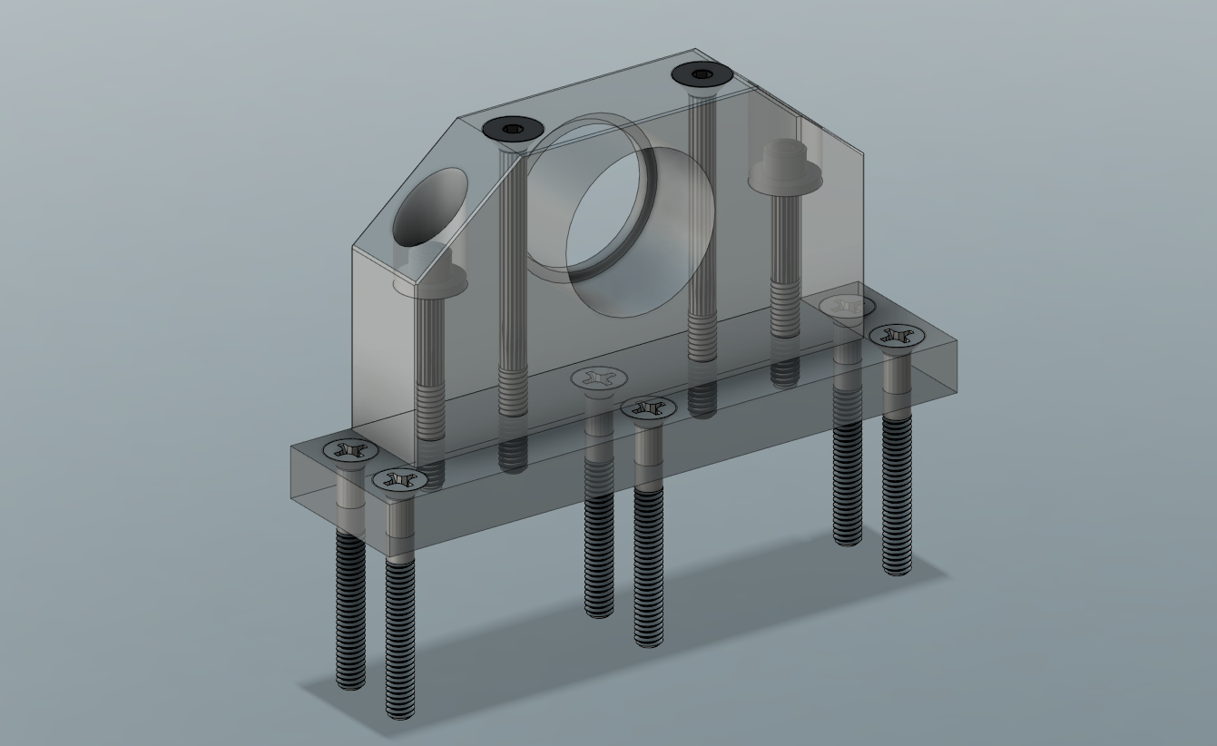
These were actually the first parts made for this machine. I feel that the bearing suppoorts are a weak point in Matthias' design. I didn't want to risk them failing, or wearing and needing replacing down the road. I also didn't feel comfortable simple screwing them into the frame, and wanted to have a method that allowed the bearing blocks to be removed. I decided on aluminum bearing blocks, which would bolt to steel plates which are screwed and bonded into the frame sides. Here's a detailed view from Fusion 360:
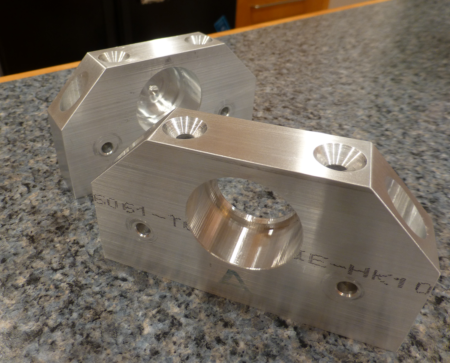
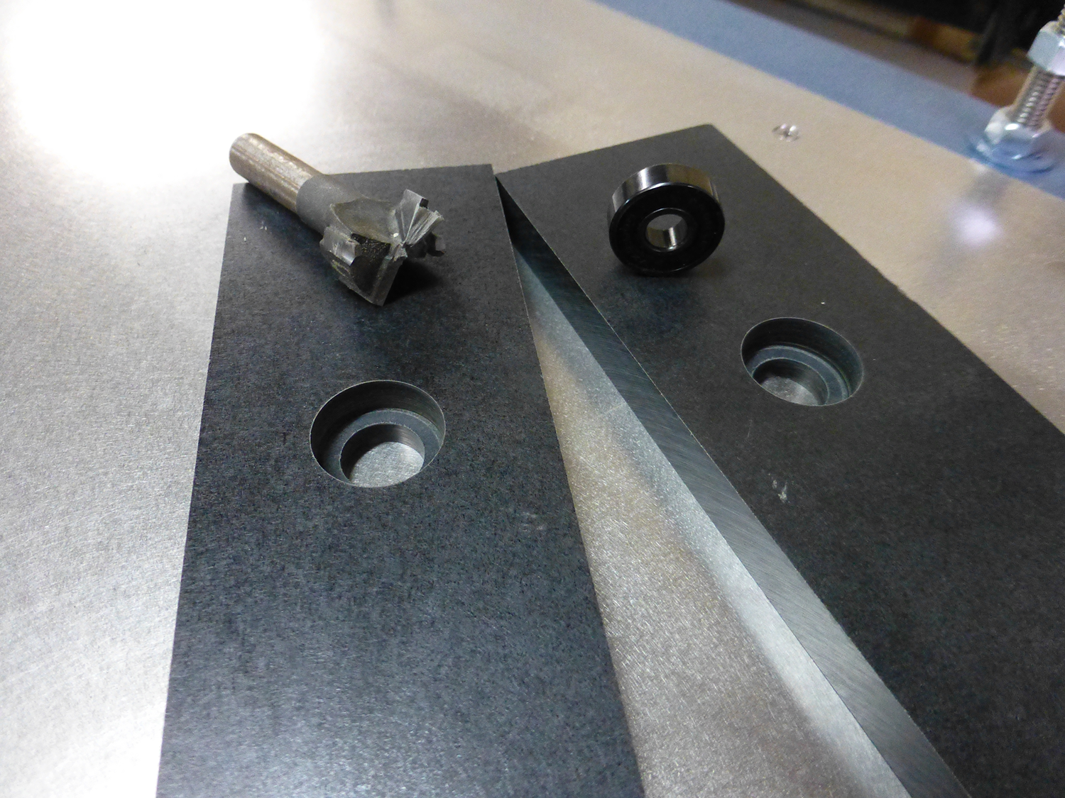
I orderd two blocks from ebay, 1" thick, and 3"x5". I drilled two holes so that I could bolt them to my CNC router's table, and machined them square. I also located the center hole for the bearing. Download bearing block pdf.
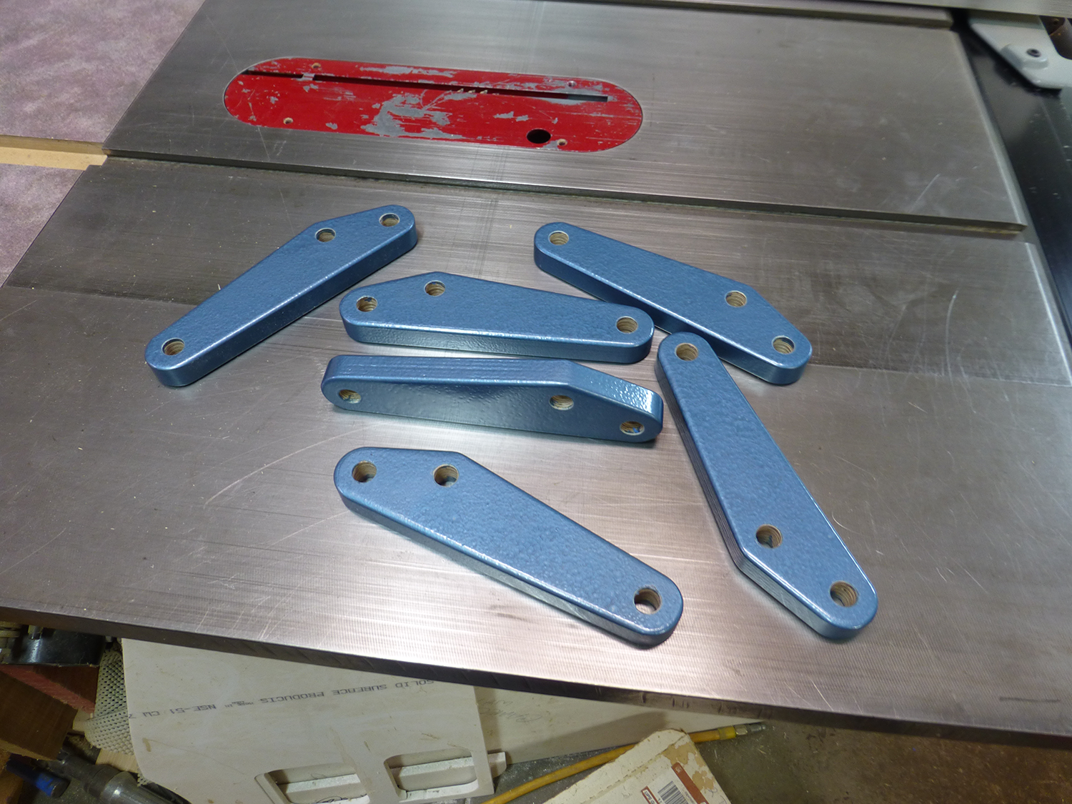
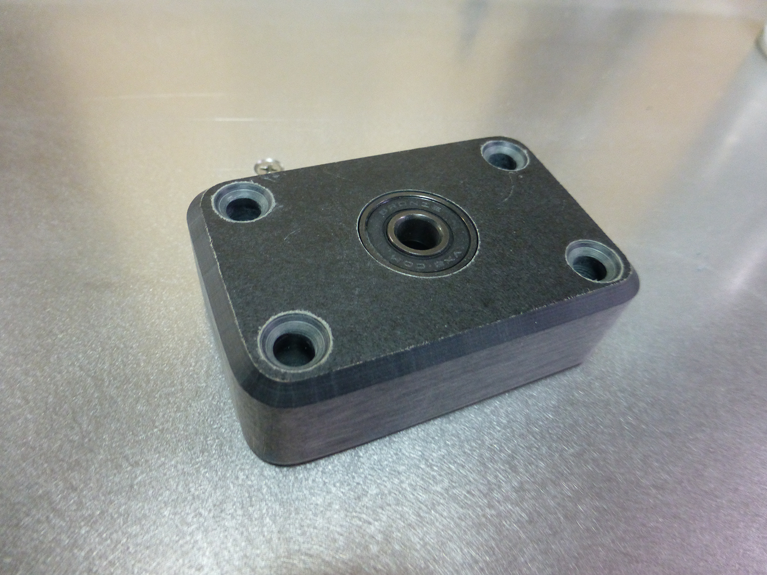
At the drill press, using a fence, I drilled the four mounting holes. Then cut the chamfered corners on the table saw with a sled, and back to the CNC to counterbore the two outer mounting holes. An hour or so of wet sanding to give them a "finished look, and I had this:
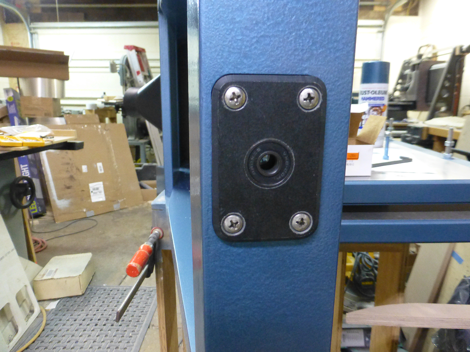
Set in place to get an idea of where they'd end up on the frame.
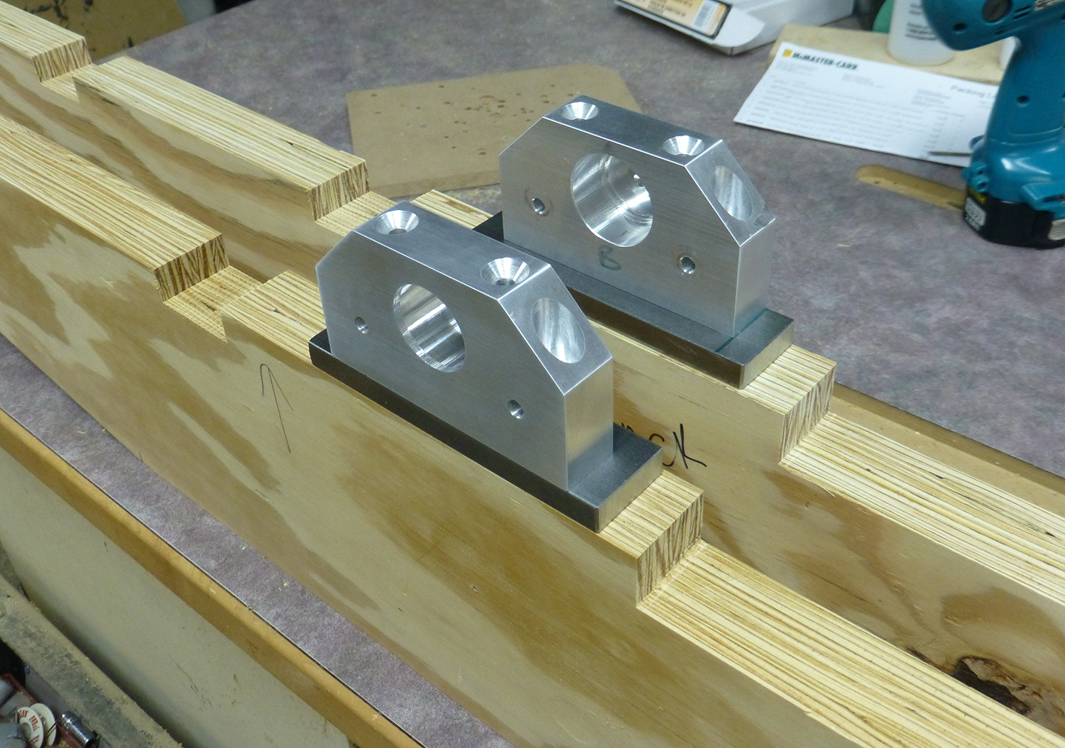
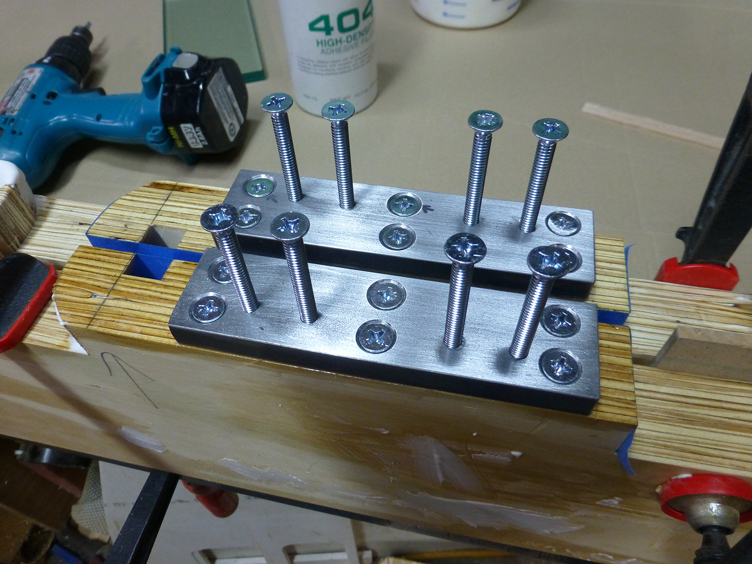
For the mounting plates, I puchased a 1/2" x 1-1/2" steel bar from McMaster-Carr, and cut it into two 6" lengths. Drilled and tapped for the four 1/4-20 mounting bolts, then drilled and countersunk six holes to attach them to the frame. I uses 1/4-20 x 3" screws, and epoxied the mounting plates (and screws) to the rails. I used some oiled screws to keep epoxy out of the threaded holes while it cured.
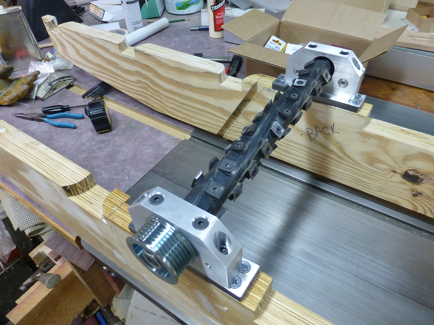
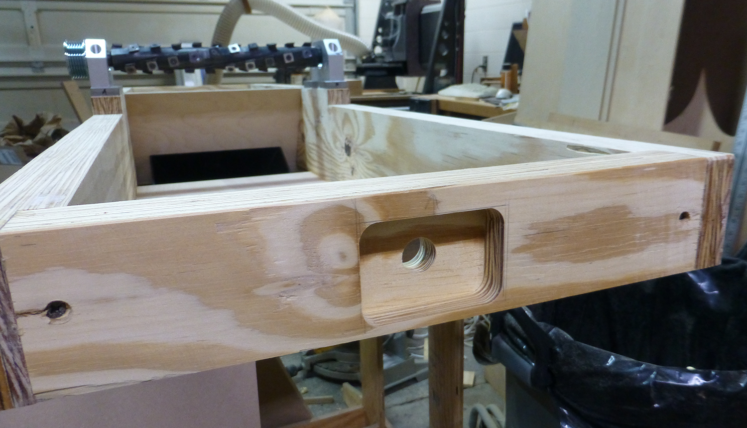
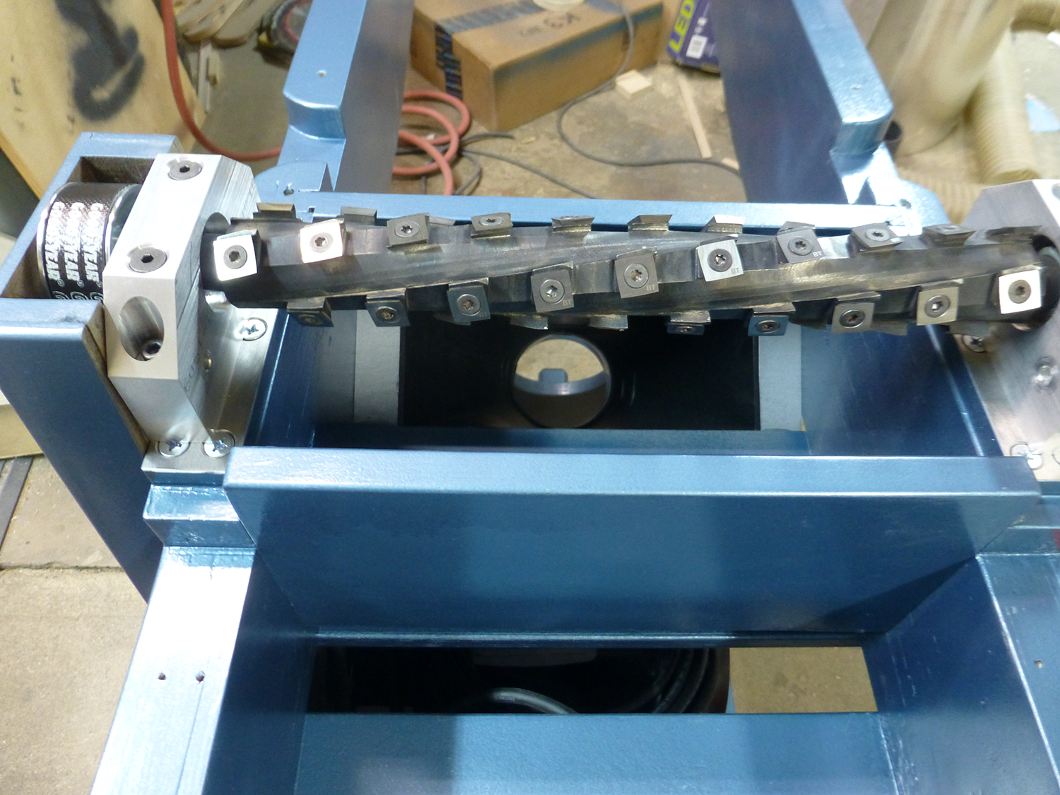
Once the epoxy set up, I installed the cutterhead into the bearing blocks, and bolted them to the frame rails. This dictated the width of the frame, and allowed me to cut the end pieces to length. Also note the angled slot, which received a baltic birch deflector plate that the dust collection hood would mount against.
Before assembling the frame, I used the CNC to route a pocket which would later accept the bearing mounts for the infeed table lifting screw.
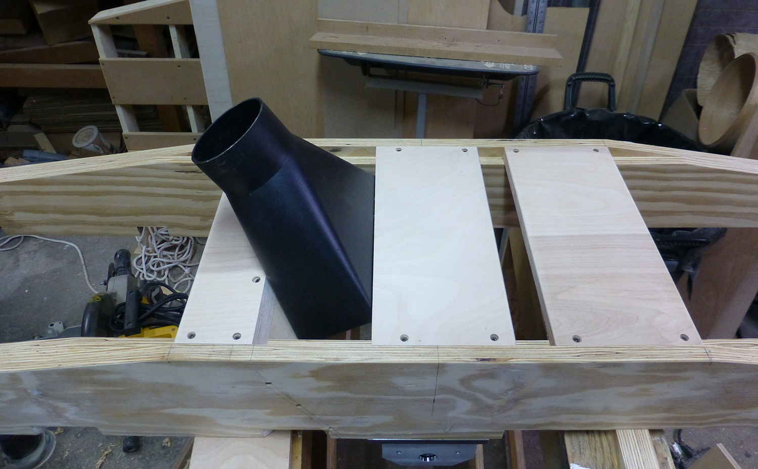
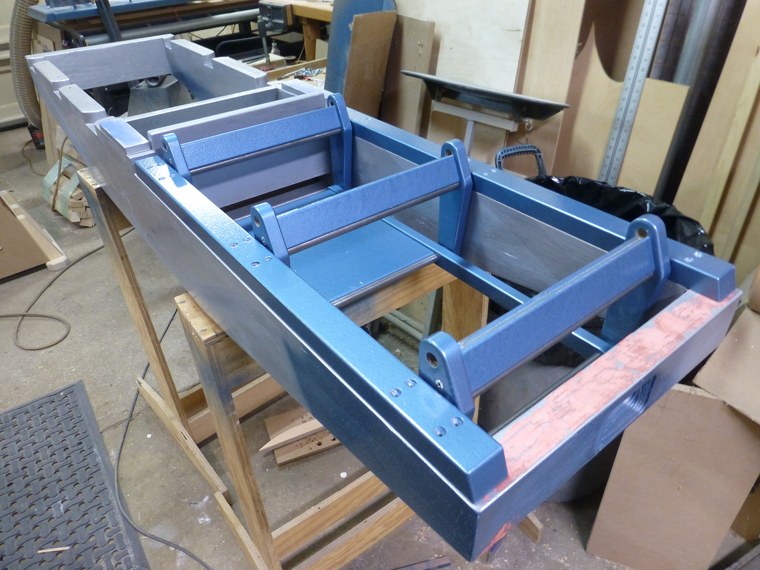
I then assembled the frame, and turned it upside down to install the bottom frame rails, which are 3/4" baltic birch. The rear rail (on the left) is angled and installed flush with the deflector plate. The center rail has an angled rabbet to accept the dust hood, which slides into place and bottoms out against the rabbet. The hood would later be installed with silicone, and small wedge blocks on each side to close the gaps and keep it from dropping.
The Base
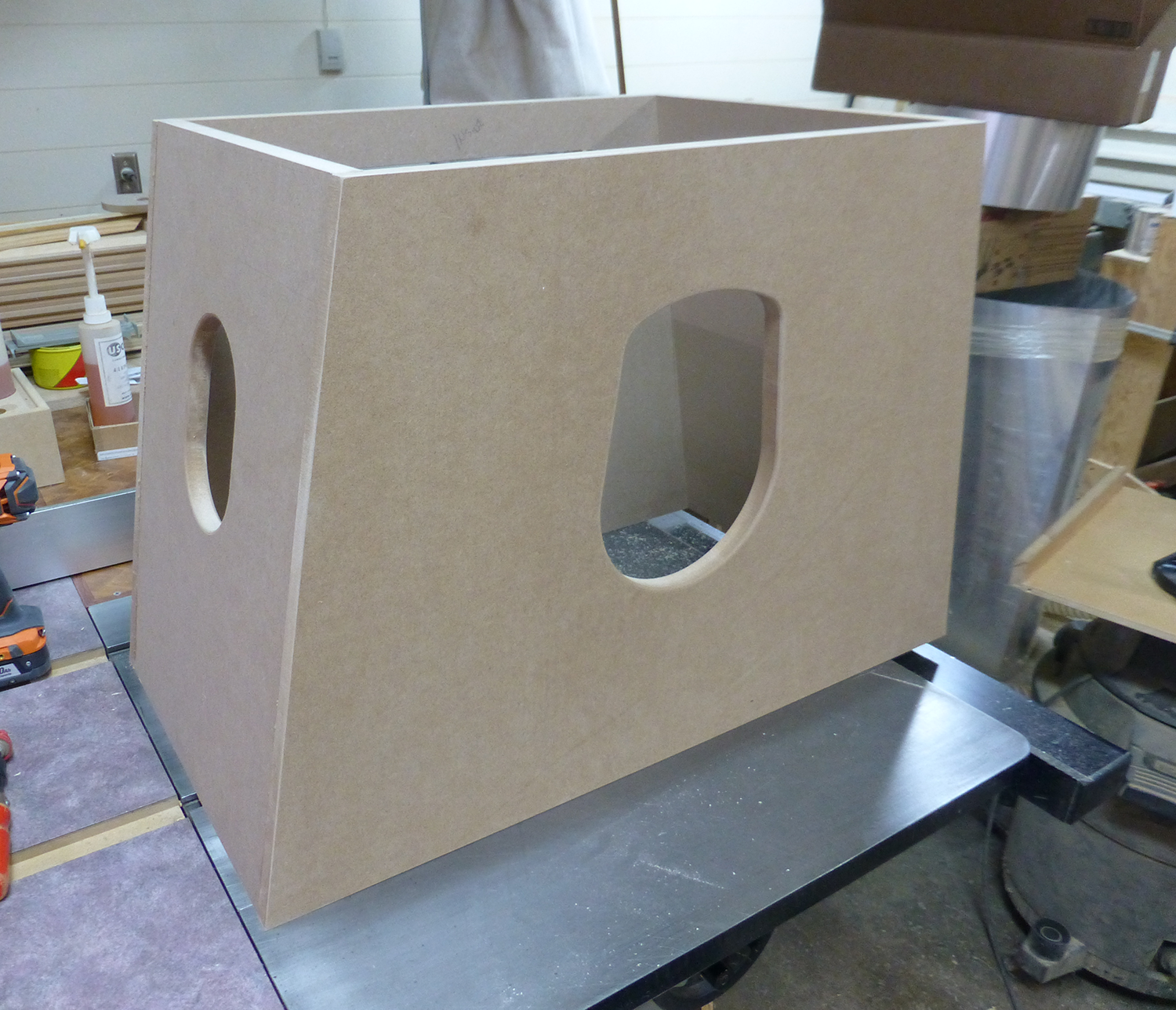
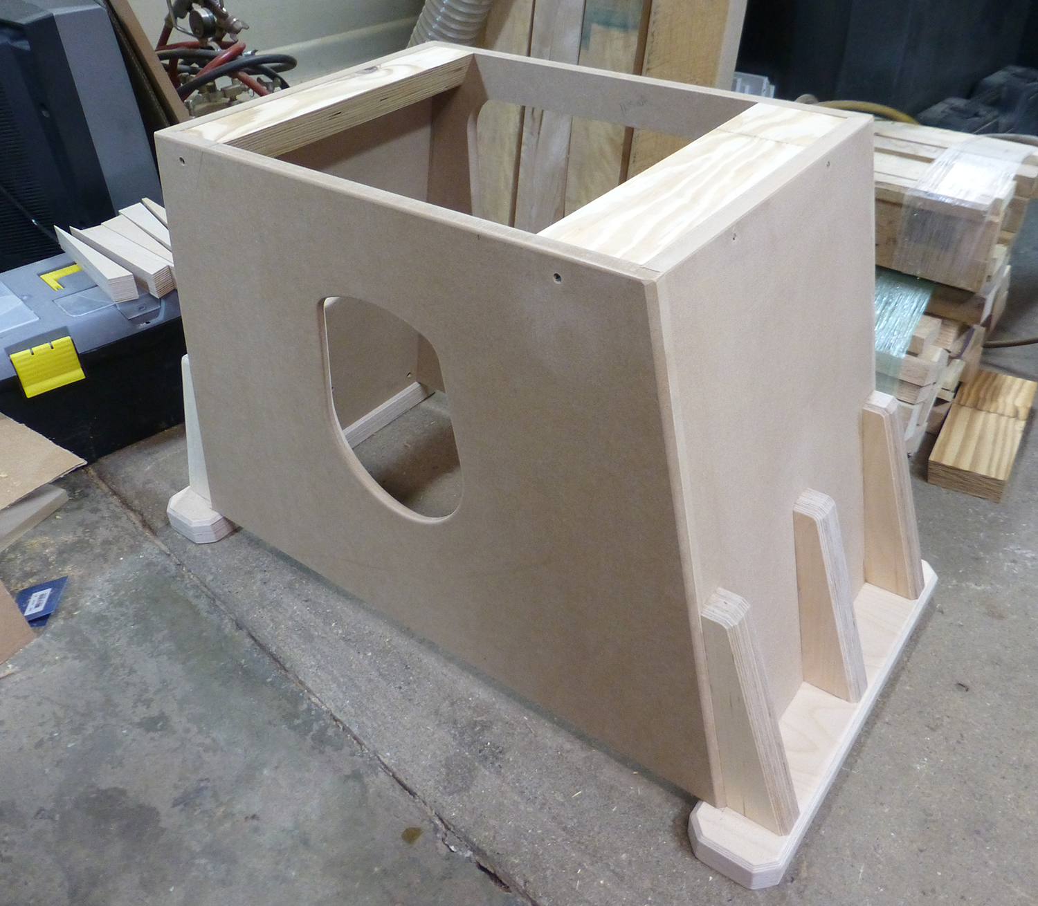
The base of the machine is made from 3/4" MDF. The front and back panels were cut on the CNC, as well as the cutout for the dust hose. Becasue MDF doesn't hold screws well, and tends to split, I rabbetted the front and back panels to accept the sides, and glued and clamped the 4 pieces together. I later glued in some corner blocks to reinforce the four corners.
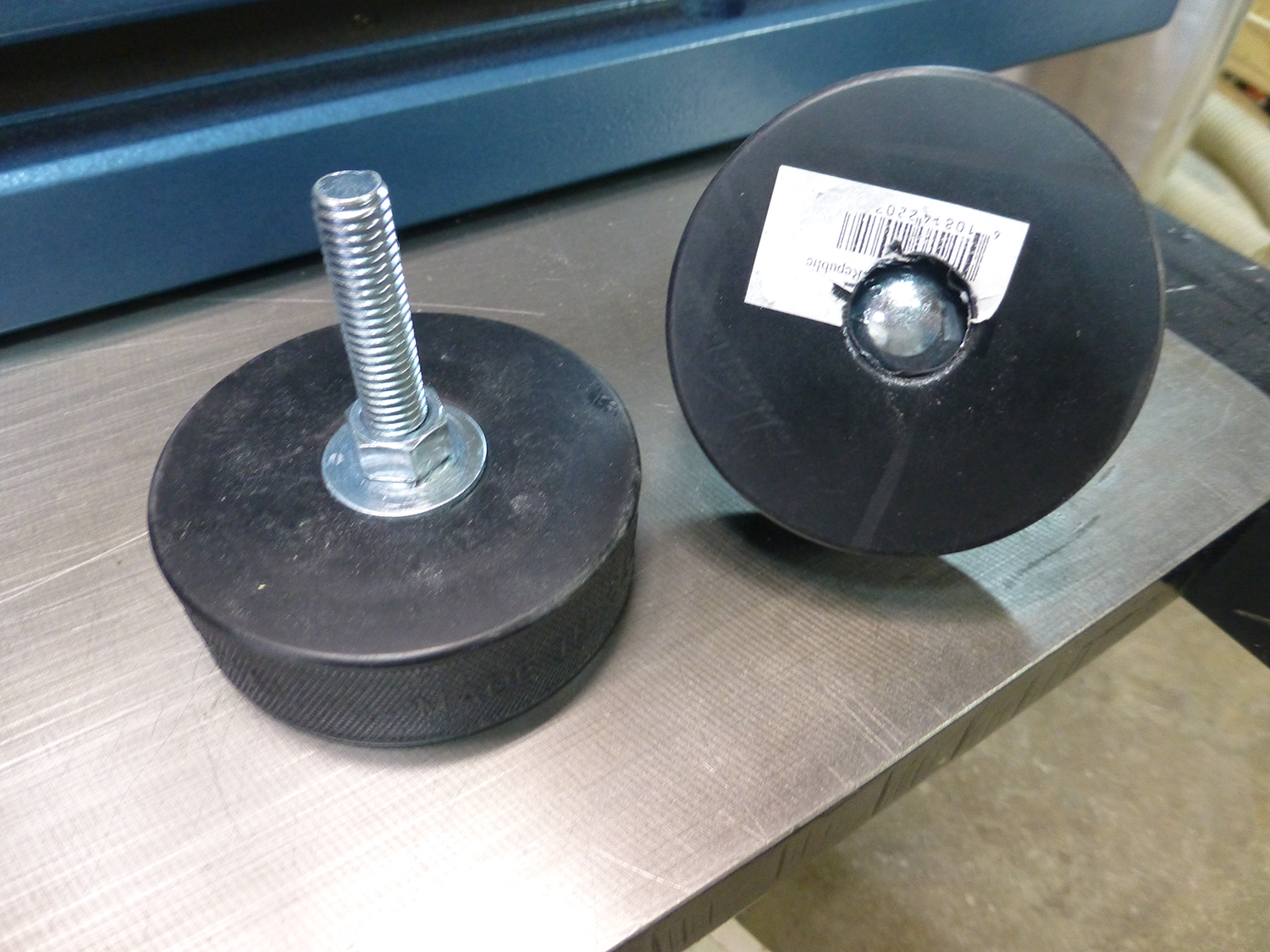
I made my own non-slip leveling feet from hockey pucks and carriage bolts. These were attached to baltic birch bottom plates, with baltic birch support brackets helping to firmly attache them to the MDF. I used the table saw and a sacrificial fence to chamfer all the baltic birch parts.
Checking the fit.
Assembled Base. I uses some of the scrap LVL's for the top rails. These would later receive t-nuts for mounting the frame to the base.
View of the frame attched to the base

The Motor Mount
I designed a simple motor mount from baltic birch, where the weight of the motor would provide the belt tension. The motor mounts to a 1-1/2" thick plate with carriage bolts, and this plate slides along another 1-1/2" plate with a key to keep them aligned. Two more carriage bolts allow the motor to be locked in place. Loosening the two nuts allows the motor to slide up and down. Four triangular brackets help to hold the motor in position. The assembly is glued to the MDF front panel, with about 12 screws assisting.
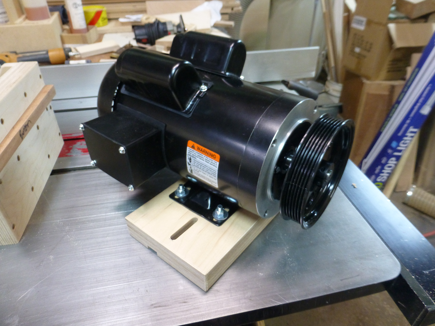
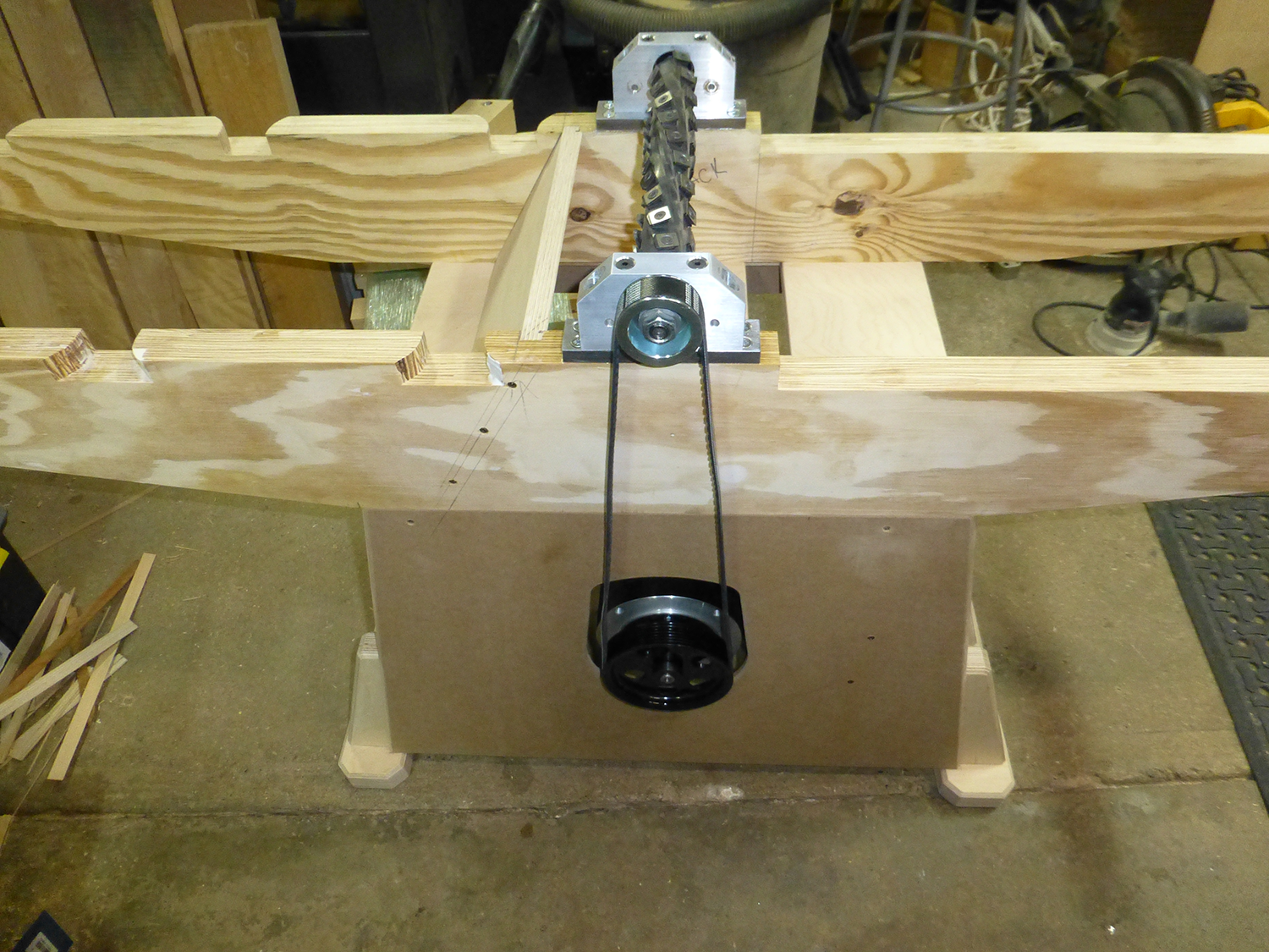
The original pulley on the cutterhead was a 6 groove Poly V "J" profile belt. The motor spun at 20,000 rpm, and the cutterhead at 10,000 rpm. With the new motor being 3450 rpm, I needed to find a rather large pulley to increase the cutterhead speed. The problem is that these can be very expensive, upwards of $100. I asked another jointer builder, medicineman007 on YouTube, what he was using, and found out that a power steering pulley would work for the motor, and an alternator pulley for the cutterhead. I went with a Dorman 300-008, which was about 5-1/2" diameter, and about $17 at Amazon. For the cutterhead, I used a 55mm alternator pulley from EBay, for about $12.
Both required hand filing a slot for the keyway into them. These gave me a ratio of roughly 2.5x, which should give a cutterhead speed of ~8700 rpm.
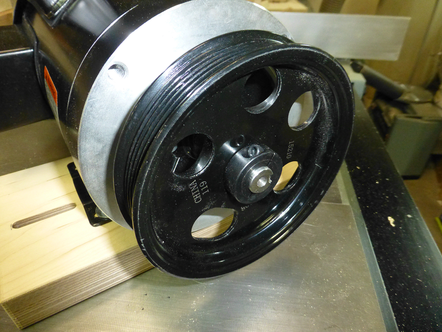
To mount the pulley to the motor, I used a pair of shaft collars, one behind the pulley, and one in front. The bore of the pulley was slightly larger than the shaft, so I used a small piece of paper for a shim, which made it fit very tight.
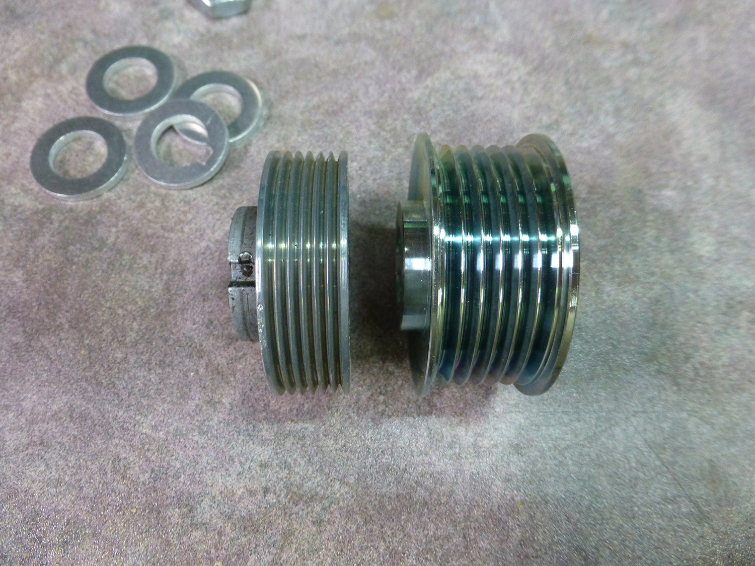
Automotove pulleys are "K" profile, which is much larger than the stock "J" profile. Here you can see the size difference.
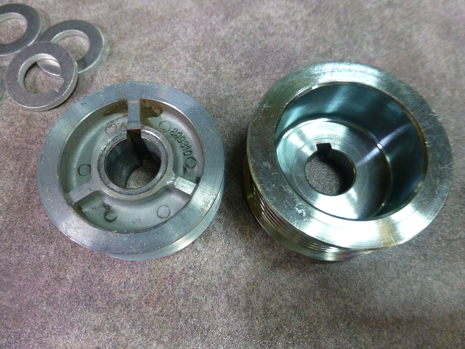
The hub on the new pulley was much shallower, so I needed to use some 1/8" aluminum washers to position the pulley in the correct location on the cutterhead. I cut the original key in half, and still had to file a keyway slot in one of the washers.
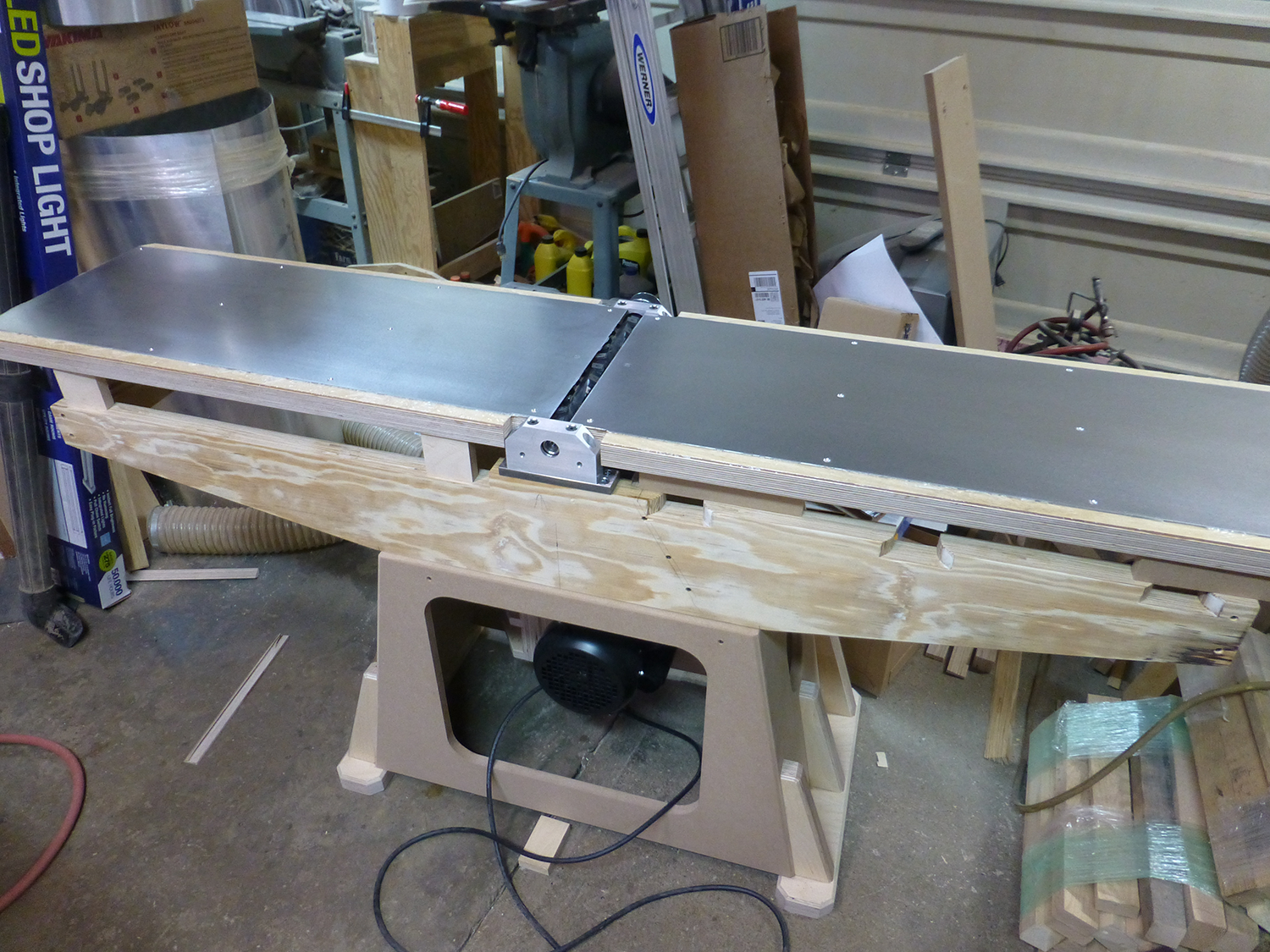
Here's a shot of the motor mounted in the base, and another with the belt loosely installed to check if it fits. This is the second belt I bought, as I improperly ordered a belt that was about twice as long as I needed originally. Belts are about $5 from Amazon. The belt is a Goodyear Gatorback, and the number is 4060500.
The Tables
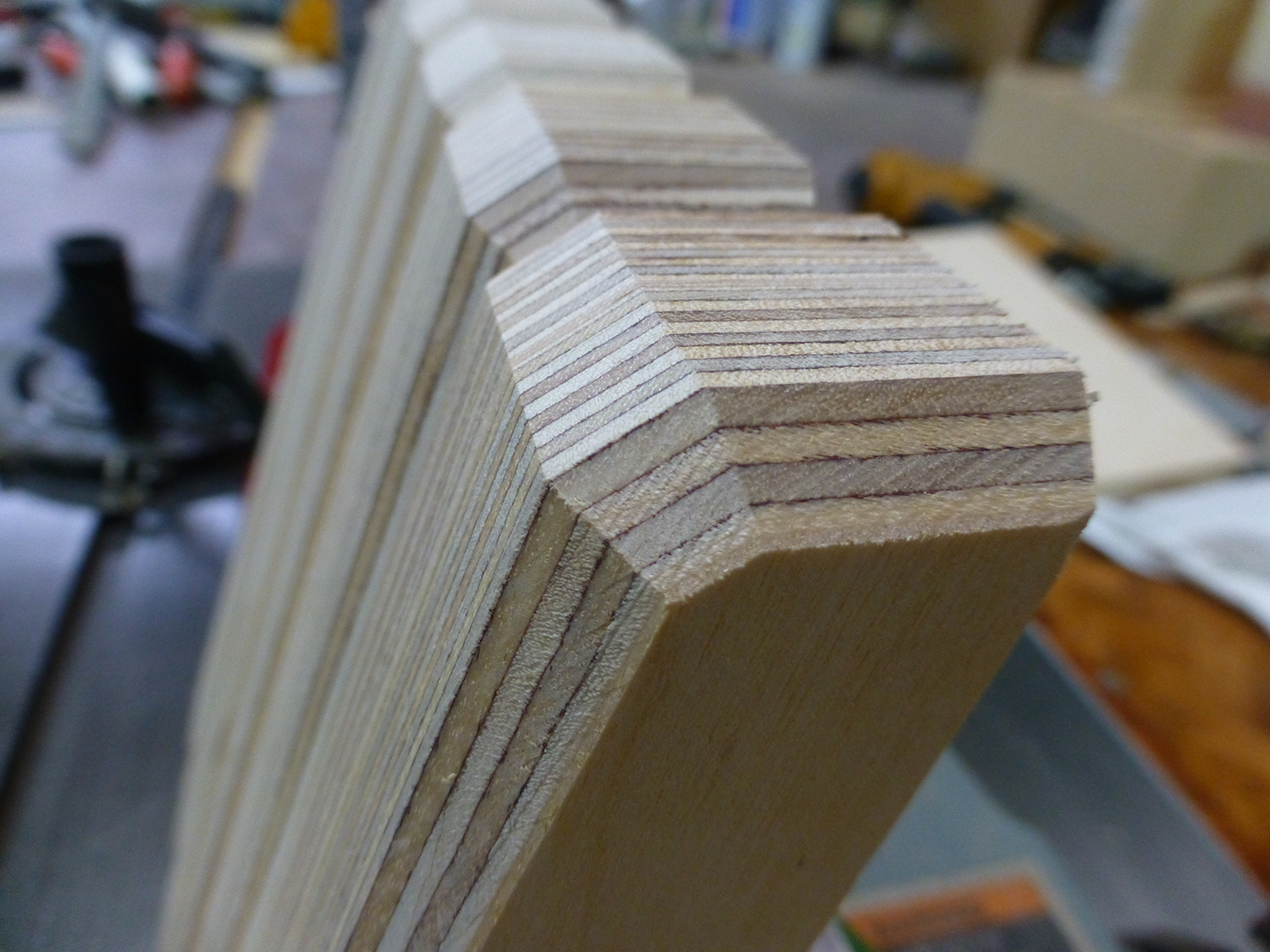
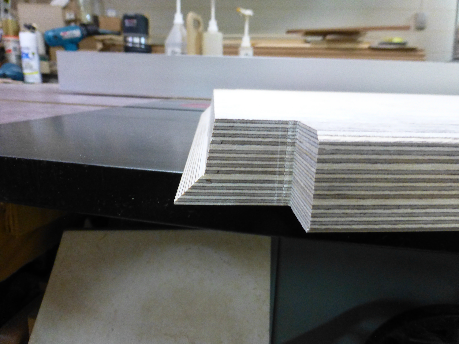
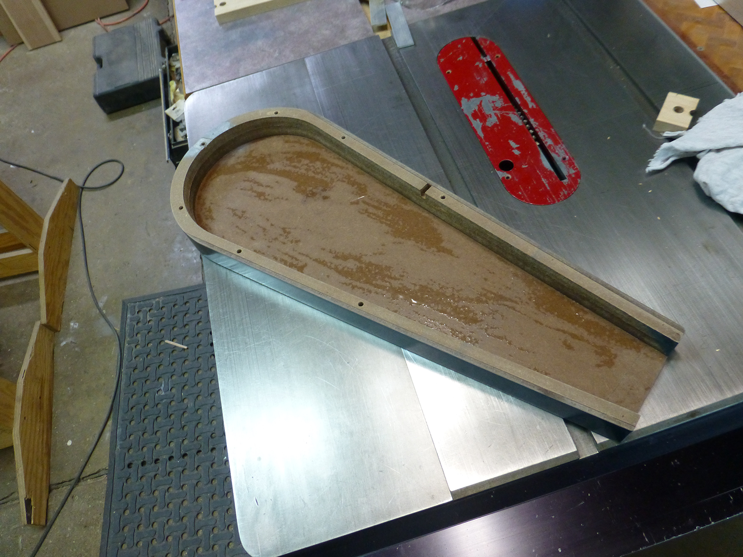
The biggest concern I had with building a jointer, was the tables. A jointer with tables that aren't flat is not a very good jointer. I was concerned that the "floating steel" method that Matthias used would not remain flat over time, and I was also unsure that I could get steel that would actually be flat when I received it. My plan was to permanently bond steel to both the top and bottom of the tables, making them torsion box type structures, with solid cores. The cores of the tables are made up of 3 layers of 1/2" (12mm) baltic birch plywood, epoxied together in my vacuum frame press. My frame press table is a torsion box that's been cnc machined flat. Unfortunately, the baltic birch I had was not very flat, and the tables had a slight warp in them after removing them from the press. I used my CNC to flatten them, removing about 1/32" from each side.
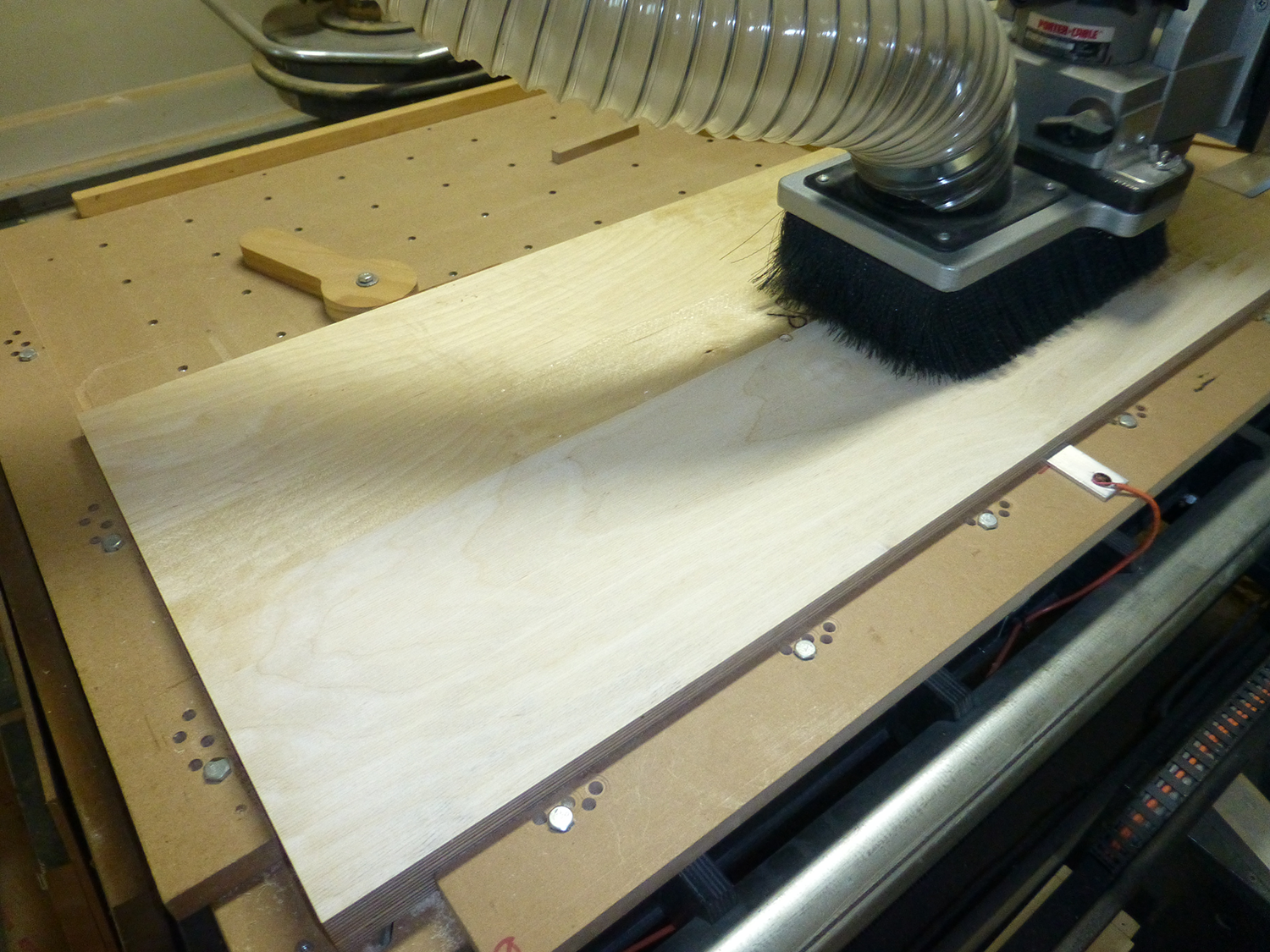
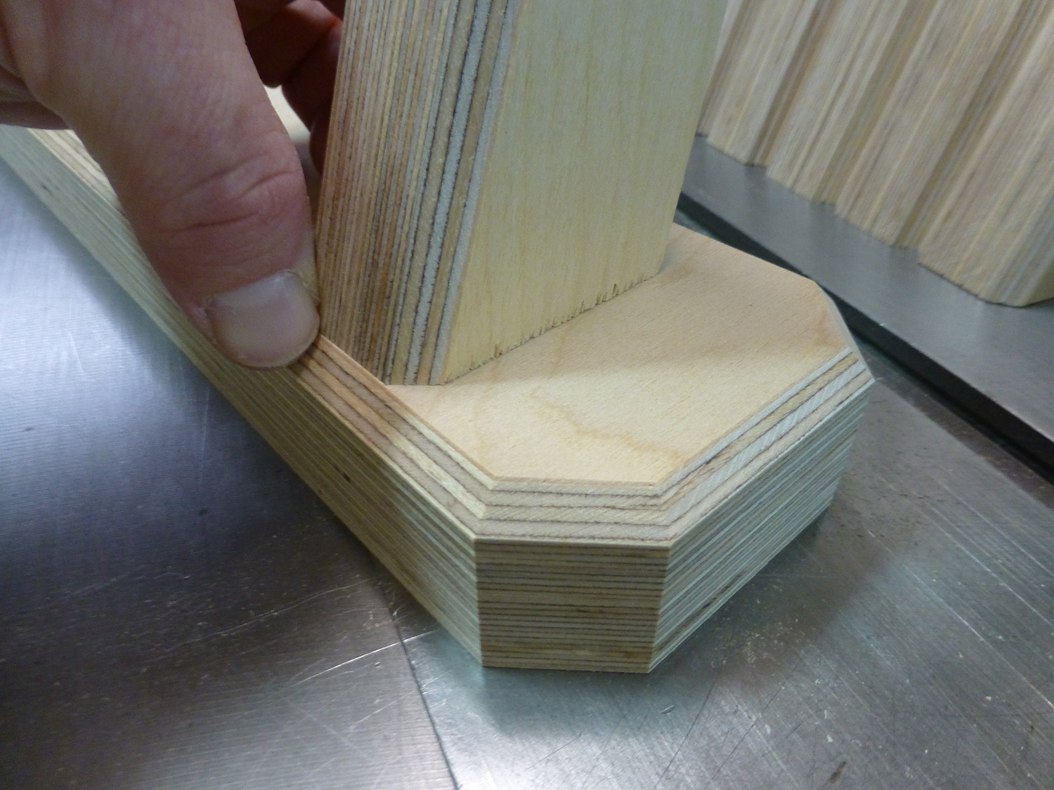
After machining them flat, I chamfered the outside corners, notched them to fit around the bearing mounts, and beveled the bottom to fit around the cutterhead.
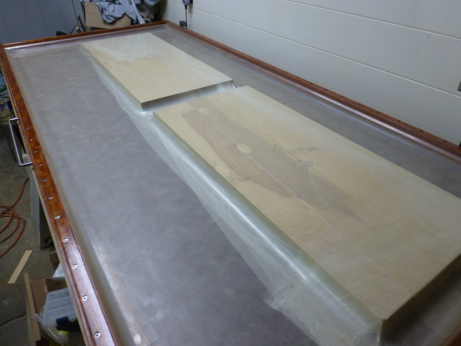
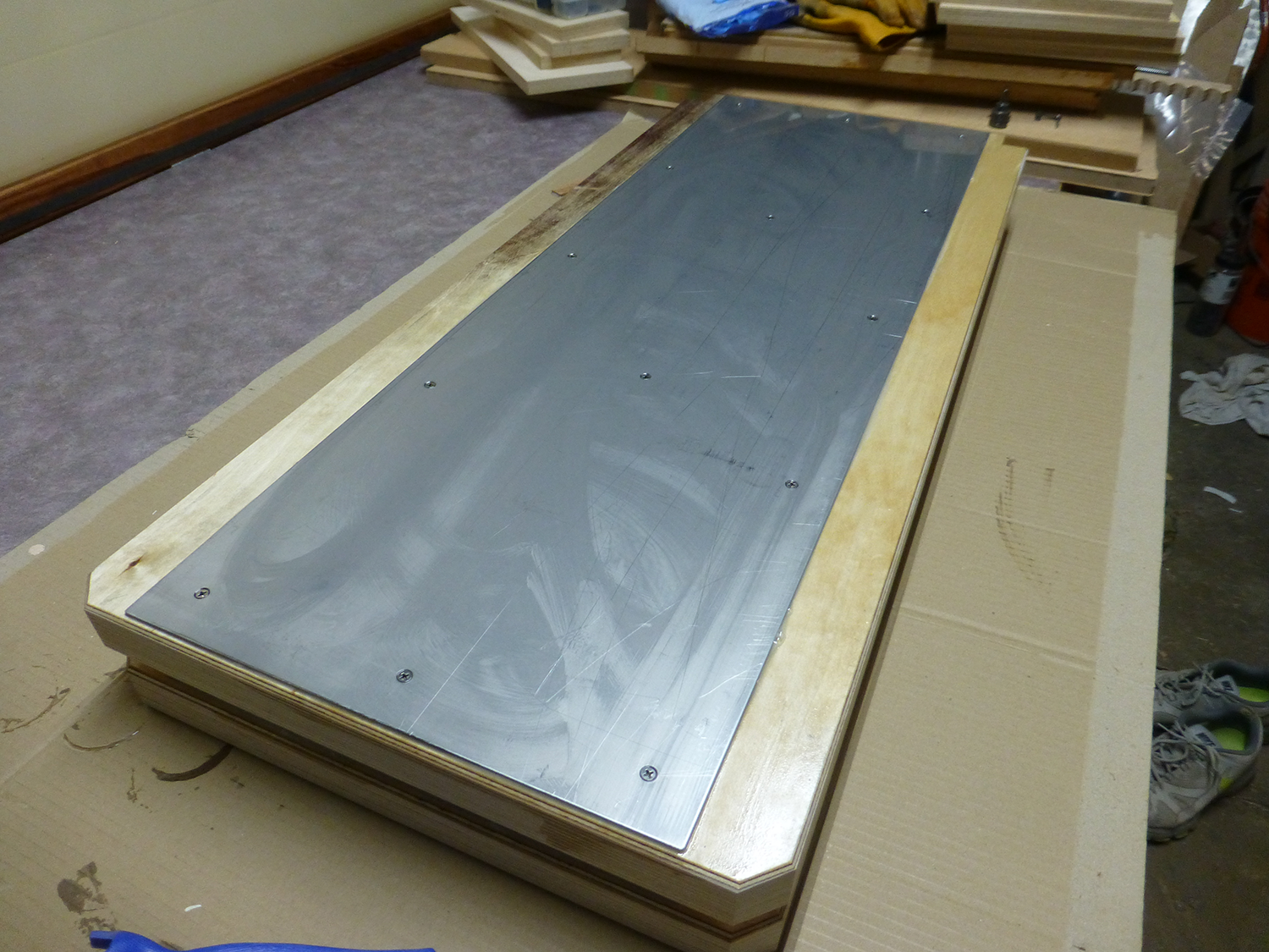
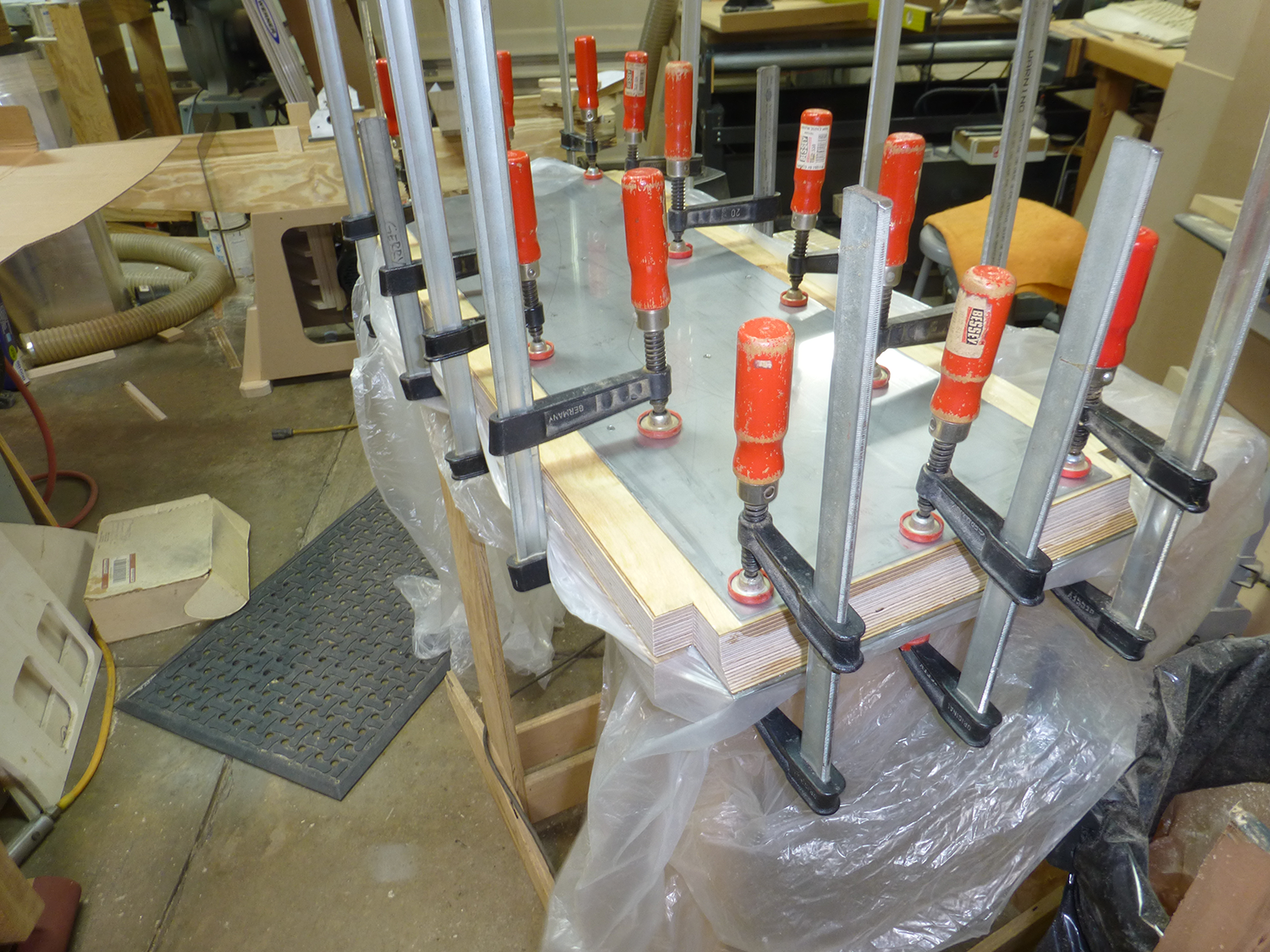
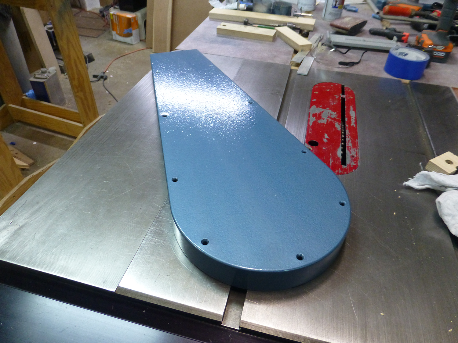
I had been searching for sources of steel for several months up to this point, and not finding what I wanted for a reasonable price. While browsing Ebay one day, I found the perfect items. 14 gauge stainless steel, $30 for 30" x 36". The nice thing was that the seller would cut them to size for free! So, I bought two, and had them cut into 13-1/2"x36" pieces, and got my four pieces for about $90 delivered. They were cut perfectly, too. Flatness was not critical on the bottom side, so I drilled and countersunk the sheets, and epoxied and screwed them to the bottoms of the tables. The next day, I was surprised at how un-flat they were. Low spots around the screws, and high spots between the screws where the epoxy was trapped. I knew I'd need a different method for the tops. I first drilled and countersunk them all. In order to keep them from moving, I used two screw in each plate, in the center at each end. I screwed them in by hand, just enough to hold them in place. I checked for flatness with a straightedge to make sure they weren't too tight. I then clamped them together, face to face, with some plastic between them to keep them from sticking together. Once the epoxy cured, I cleaned up the holes, and epoxied the remaining screws in place.
After I pulled them out of the clamps, I set the tables in place with some spacer blocks to see if everything would fit OK.
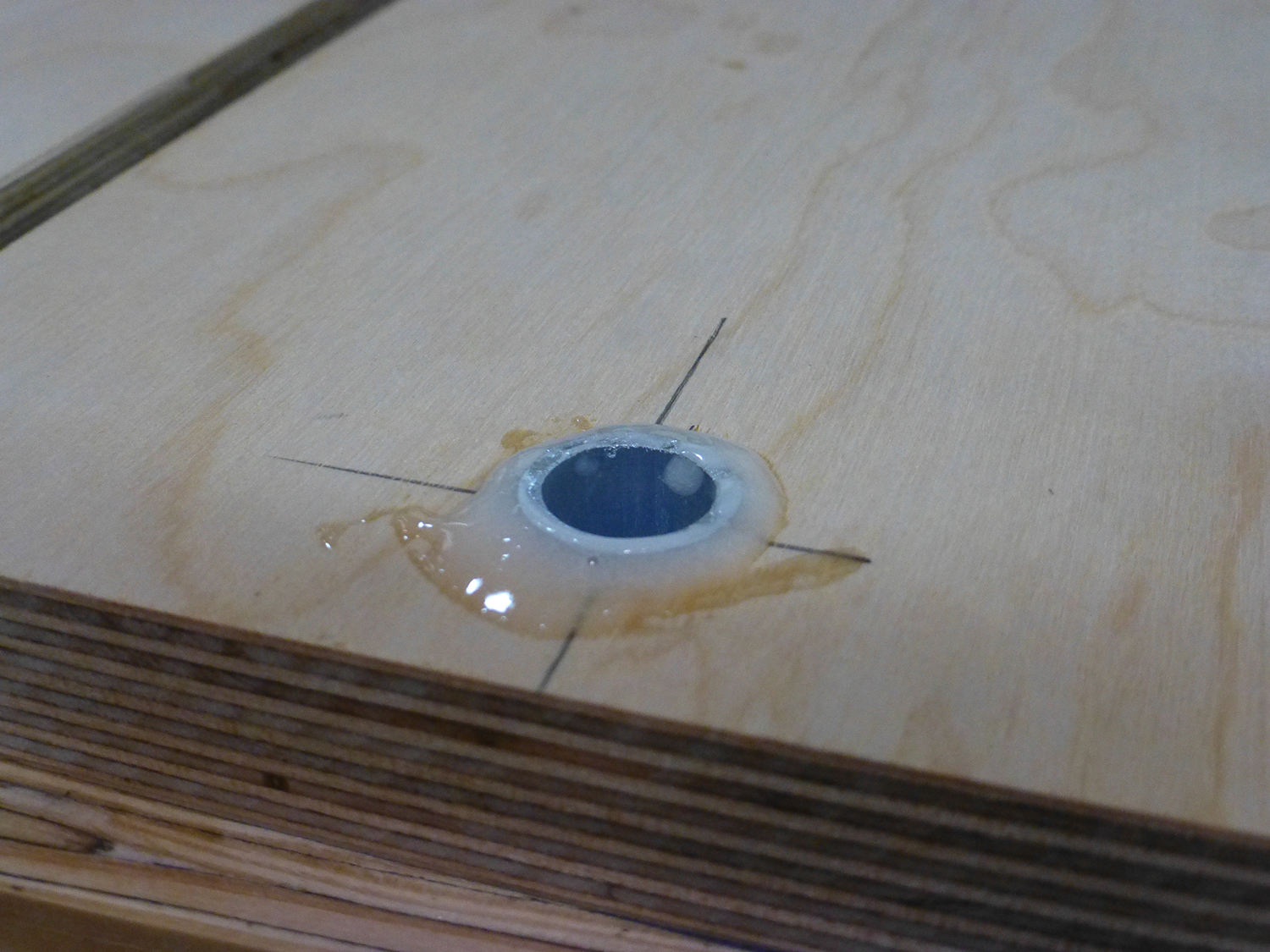
The outfeed tables are mounted with threaded studs, which are embedded into the table. I used 5/16 threaded rod. The double nuts are to drive it in with an impact driver. The bottom nut is epoxied into a counterbore. The original design used 4 mounting studs, but with my longer tables, I used six. This allows me to adjust out any bow or twist in the outfeed tables.
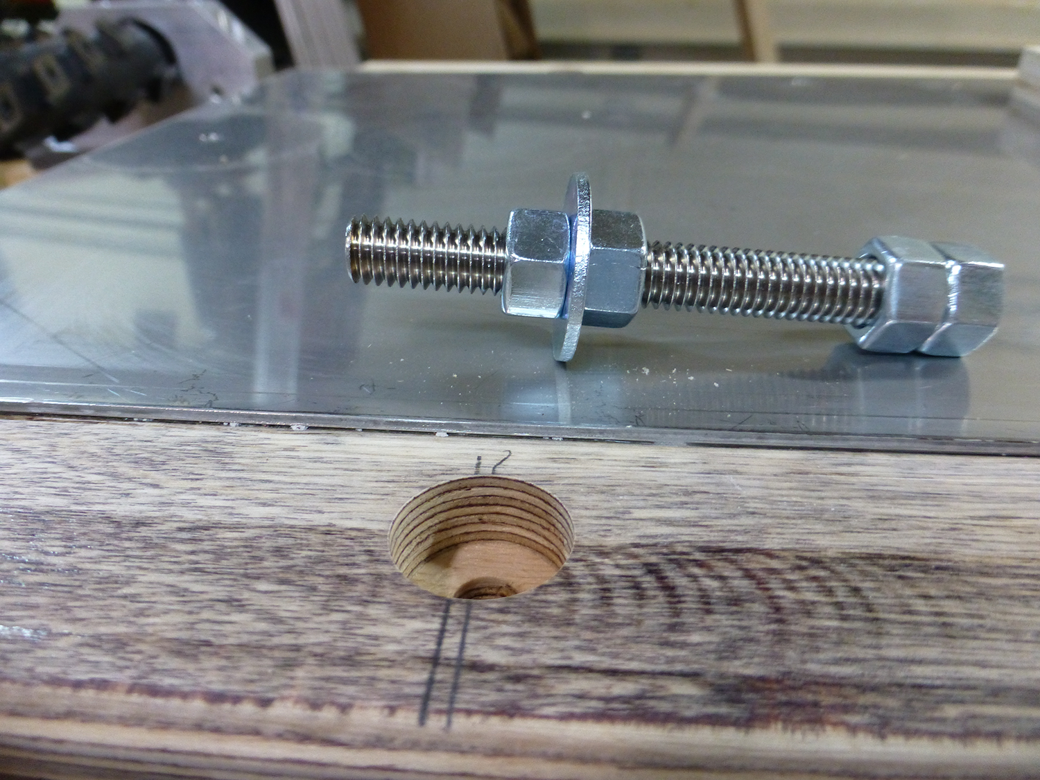
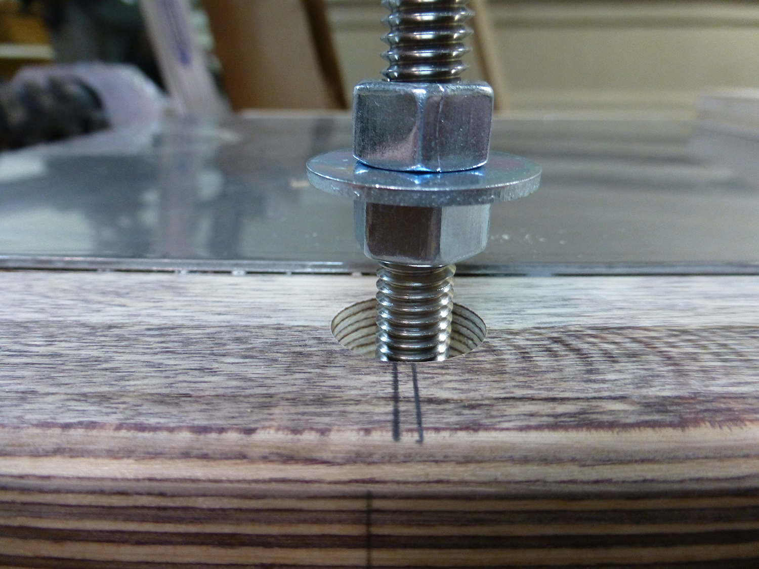
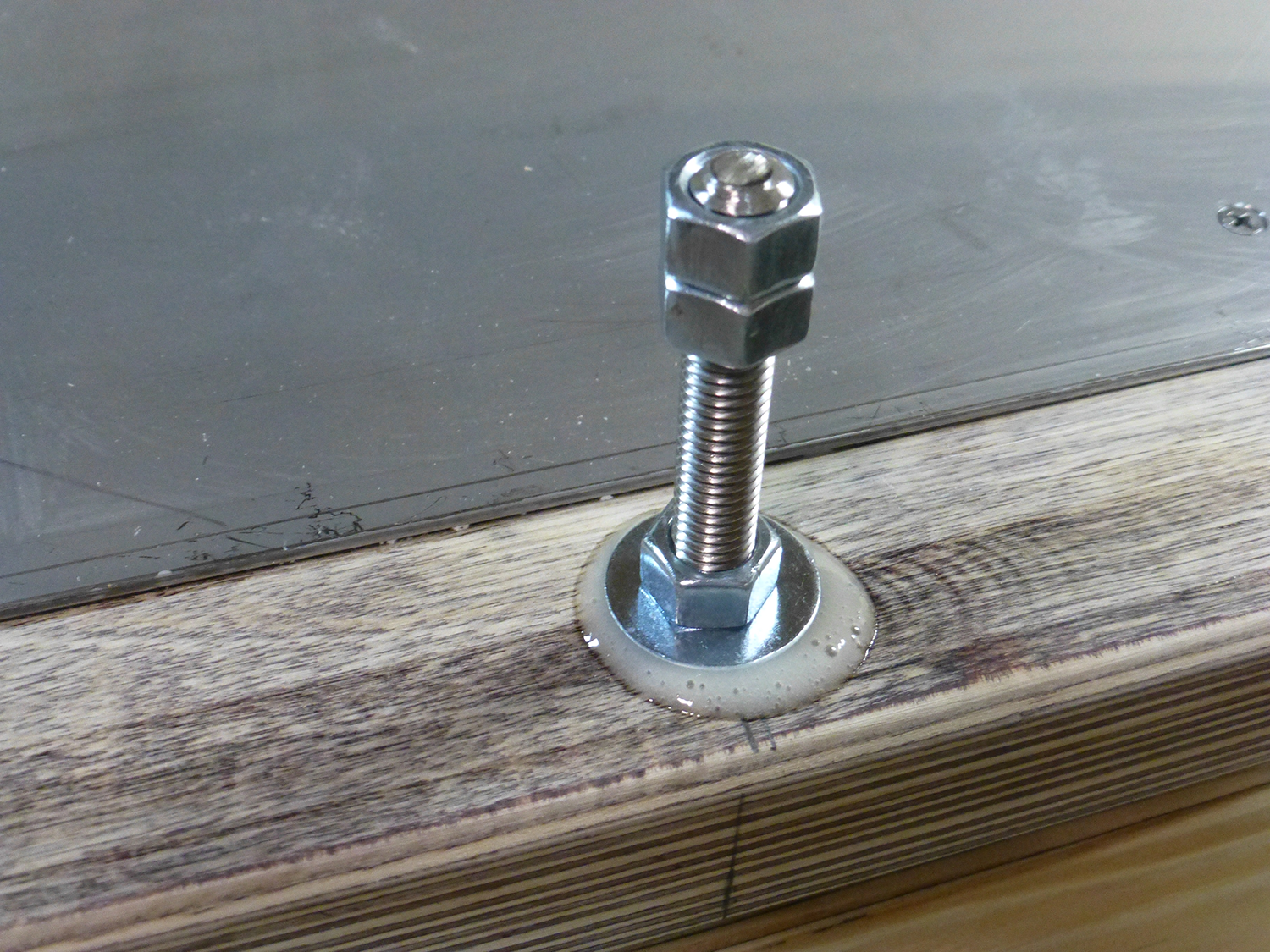
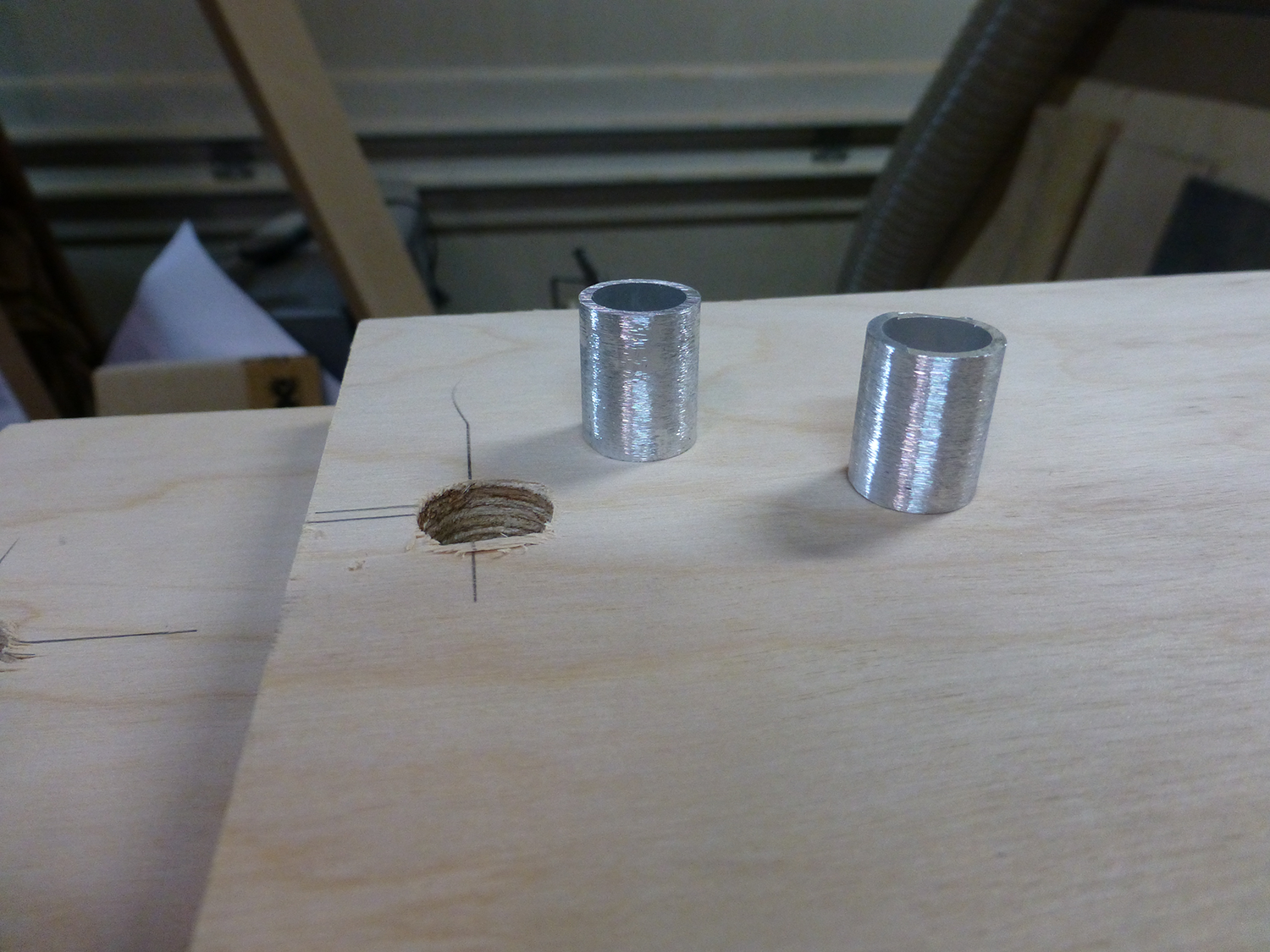
The threaded rods are supported by and mounted to 3/4" baltic birch rails. I don't like to tighten nuts and other hardware to wood, as it will usually crush the wood, and loosen over time. To prevent this, I lined the holes in the rails with aluminum tubing. This allows me to tighten nuts against both sides of the rails without it being crushed.
Before drilling the holes in the tables, I had attached the rails to the bottom of the table with double sided tape, with spacers between them. The holes were drilled through the rails and into the tables at one time, to make sure everything was aligned.
After adding my aluminum tubes, I used the same spacers to drill the rail mounting holes into the frame. The rails are removeable, mounted with the same 3" long 1/4-20 screws that I used to mount the bearing block mounts. These are machine screws, driven into untapped 3/16" holes in the frame.
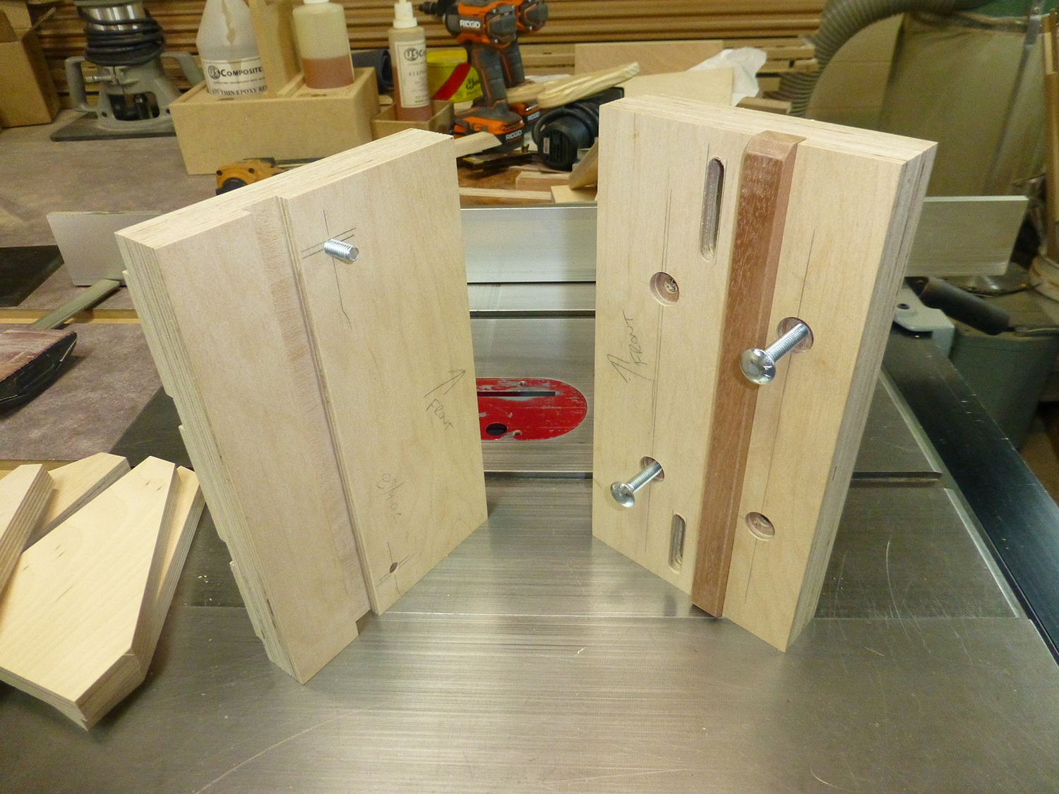
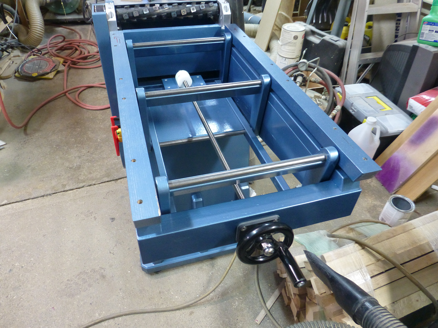
The infeed table is mounted with a screw driven parallelogram, similar to Matthias' original design. Enhancements include additional parallelogram links (6 vs 4), larger 1/2" dia, steel rods, and a 1/2-8 acme lifting screw, mounted with ball bearings for smooth movement. The higher pitch of the acme screw requires about 40% fewer turns to raise and lower the table.
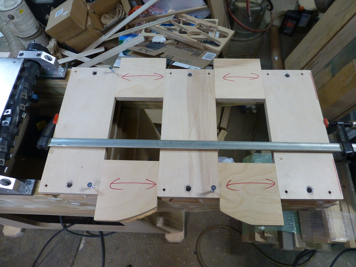
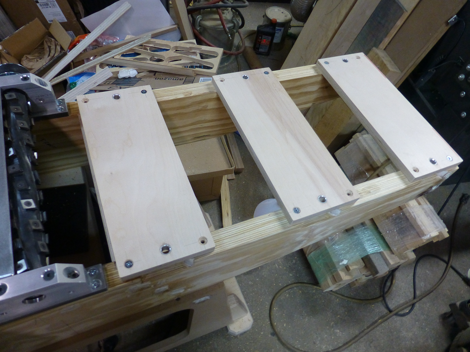
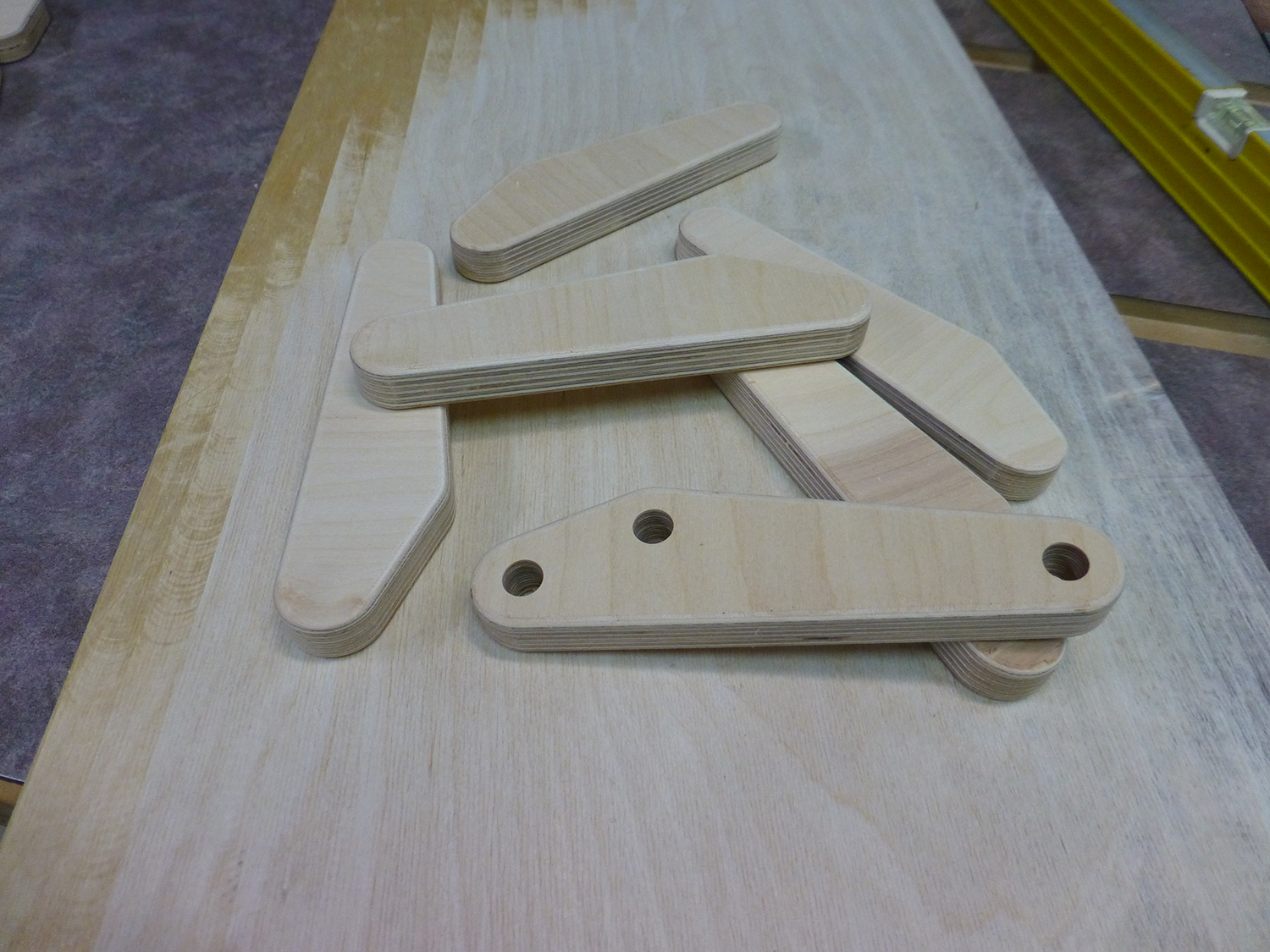
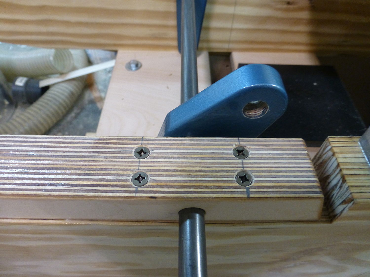
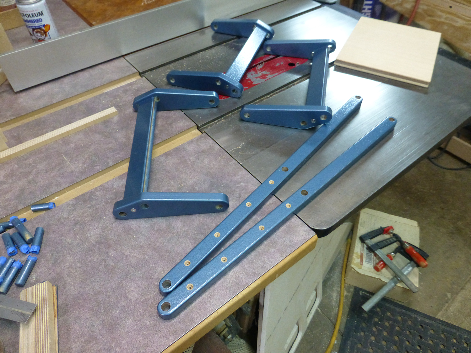
I cut the parallelogram links from 3/4" baltic birch on the CNC. I cut one extra to use as a template, and drilled 1/8" holes to locate the holes. To get a tight fit, I ground down an old 1/2" forstner bit I had by chucking it in my cordless drill, and spinning it against my 6"x48" belt sander. The template was screwed to each link, and the three holes were drilled on the drill press, giving me 6 identical links. The screw holes from the template were filled prior to painting.
The rails that support the link were glued up from two layers of 3/4" baltic birch. If I had a working jointer at the time, I probably would have made them from hard maple. I drilled the first one with a fence on the drill press, and used that one as a template for the others, as the holes in all 4 must be the same. The bottom rails were screwed to the frame on each side of the rods, so they couldn't flex and lift at all. Here's a picture of a test fit. (Note that the link is installed backwards in this pic, as well as many others. I had a recurring issue of assembling the parallelgrom with the links backwards.)
Painting.
At this time during the build process, I had started on the painting. When you look at any DIY project, the finish is often what separates good projects from exceptional ones. Good quality finishes take a lot of time, and the quality of a painted wood finish is dependent on the preparation of the wood prior to painting.
While I wanted a better than average finish, I didn't want to spend too much time, as this is after all a tool that will likely get banged up over time. I chose to use Rustoleum's Hammered paint, as it tends to hide minor imperfections, and is very durable when fully dried. I used rattle spray cans for this entire project, which presented another minor issue. Hammered paint needs to be applied thick, and even, in order to get a nice, even "hammered" look. While that's fairly easy to do on small parts, it's difficult to do on large areas, like the base of the jointer. Mainly because it's hard to spray a heavy coat on a large area without it dripping, and to apply successive passes vefore the previous ones start drying, which leaves overlapping lines. One way to avoid this is to spray it on very heavy, and go over it with a roller.
But I ran into a small problem.
I had purchased a case (6 cans) of this paint a few years ago, and started the project with about 5-1/2 cans. As I was painting the frame, It looked like I might need another can or two. When I went online to order more, I found out that the color, Deep Blue, is no longer available.
I thought about painting the base white or silver, but I thought that if I used another color as a primer/base, I'd have enough blue to finish, which I did. Hammered Silver is readily available locally, so I used that as a base coat.
Paint Prep.
Anyone that's painted plywood or MDF knows that that it can be difficult, especially when it comes to the edges. Everyone has theier methods of filling and/or sealing the edges prior to painting, but I like mine best.
I simple mix up some epoxy, and brush it on all the edges. For MDF, I also seal the faces with epoxy as well. The epoxy I use is from US Composites, and it's very inexpensive, as far as epoxy goes. I use the thin 635 epoxy, and generally use the medium hardener. I always have a half gallon on hand. Mixed with various fillers, it can be used for a variety of applications. I use it as a filler, a sealer, for bonding metal parts to wood, and as an adhesive.
All of the baltic birch parts on this machine had their edges sealed with epoxy, and were basically finished with 2 double coats of paint. The first 2 coats are done together, about 20 minutes apart, then allowed to dry overnight. The next day, they get a light sanding, followed by a light to medium coat. After another 20 minutes, one final heavy coat.
It's really a pretty simple process, and gives very good results.
Back to the build.
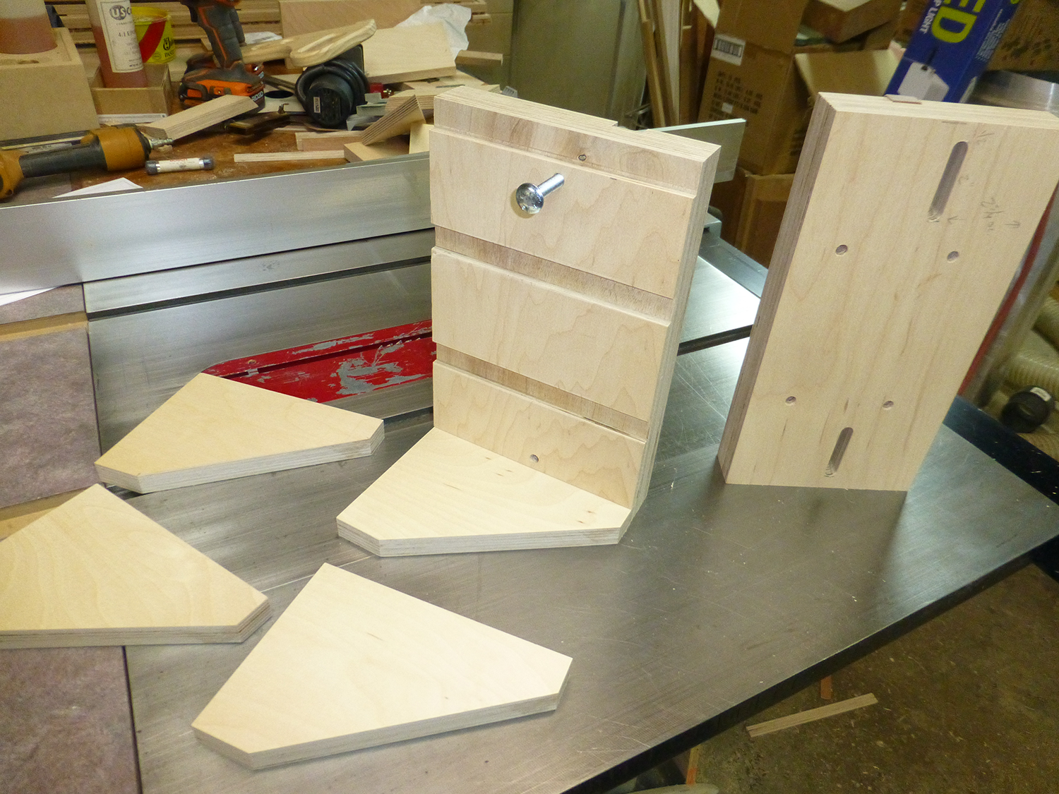
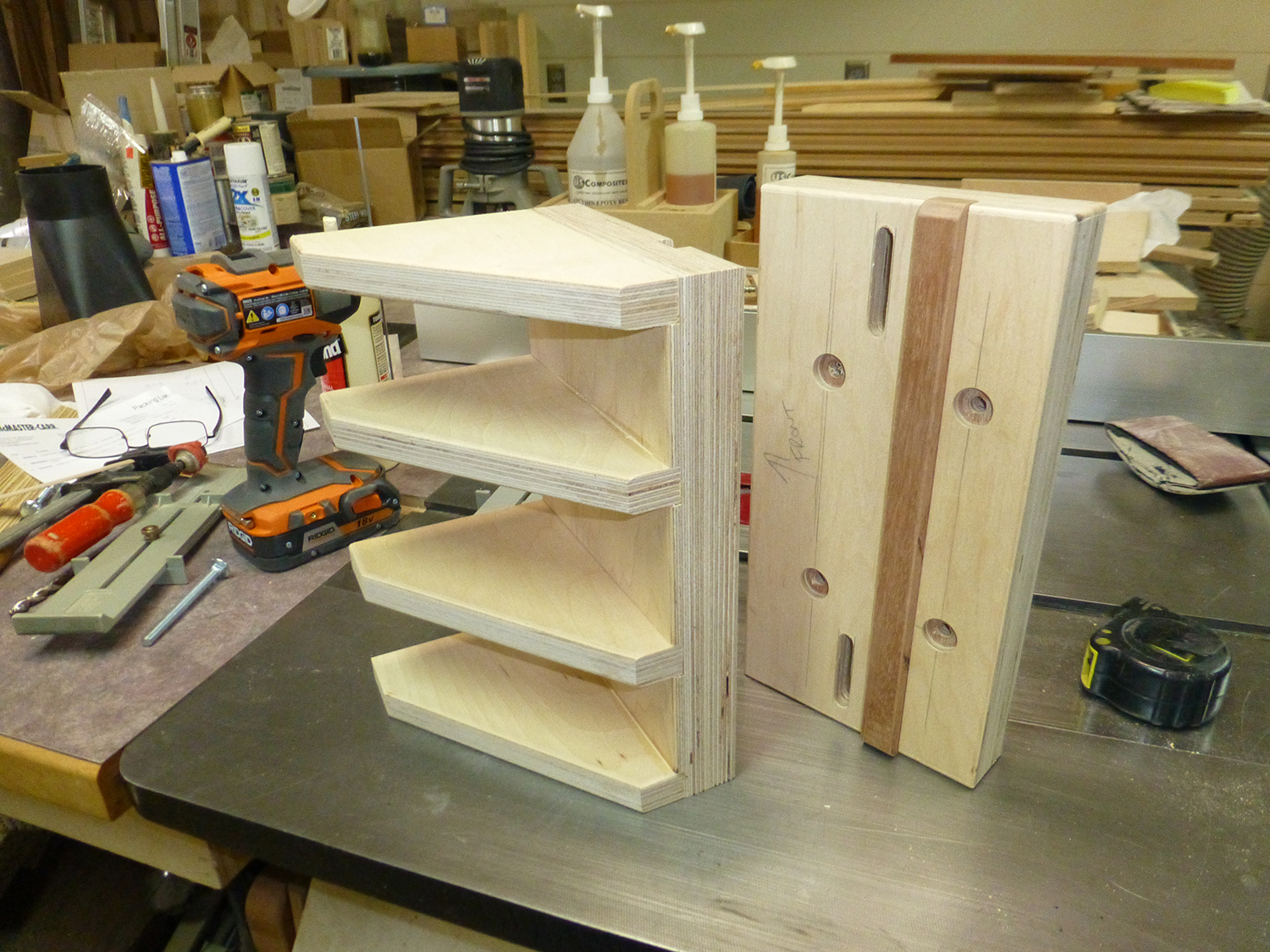
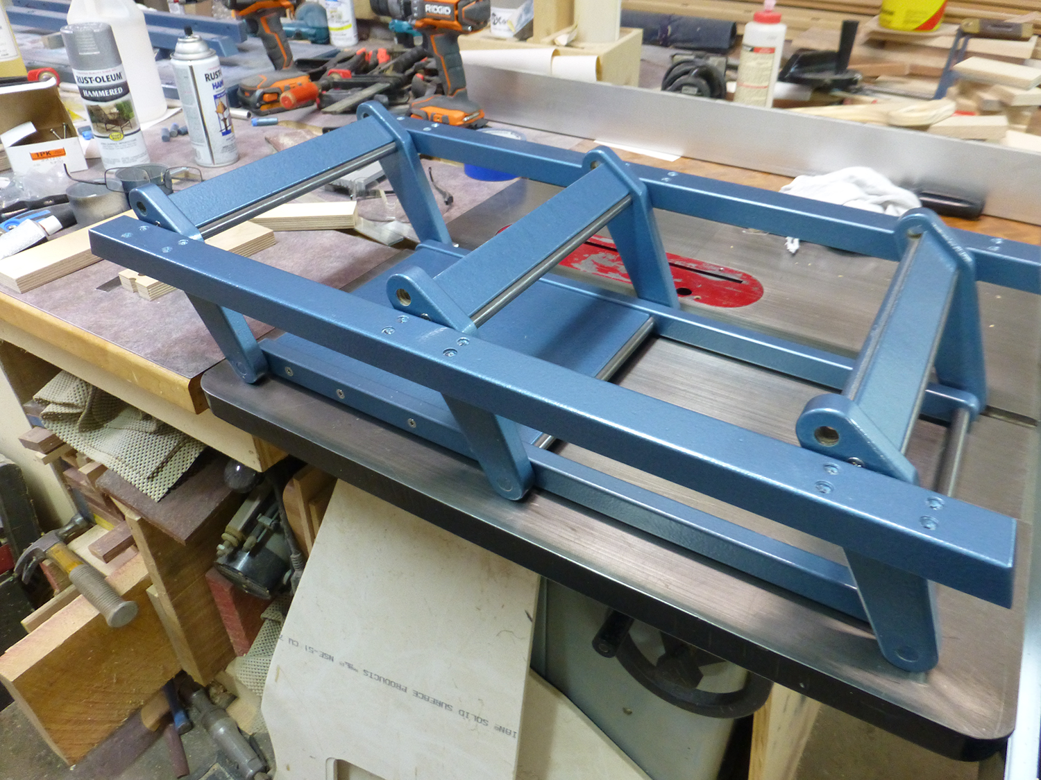
While I'm not entirely sure if they are needed, I added the spacer plates between the steel rods. 3/4" baltic birch, with the edges routed to accept the rods. I used a 1/2" core box bit in a router table.
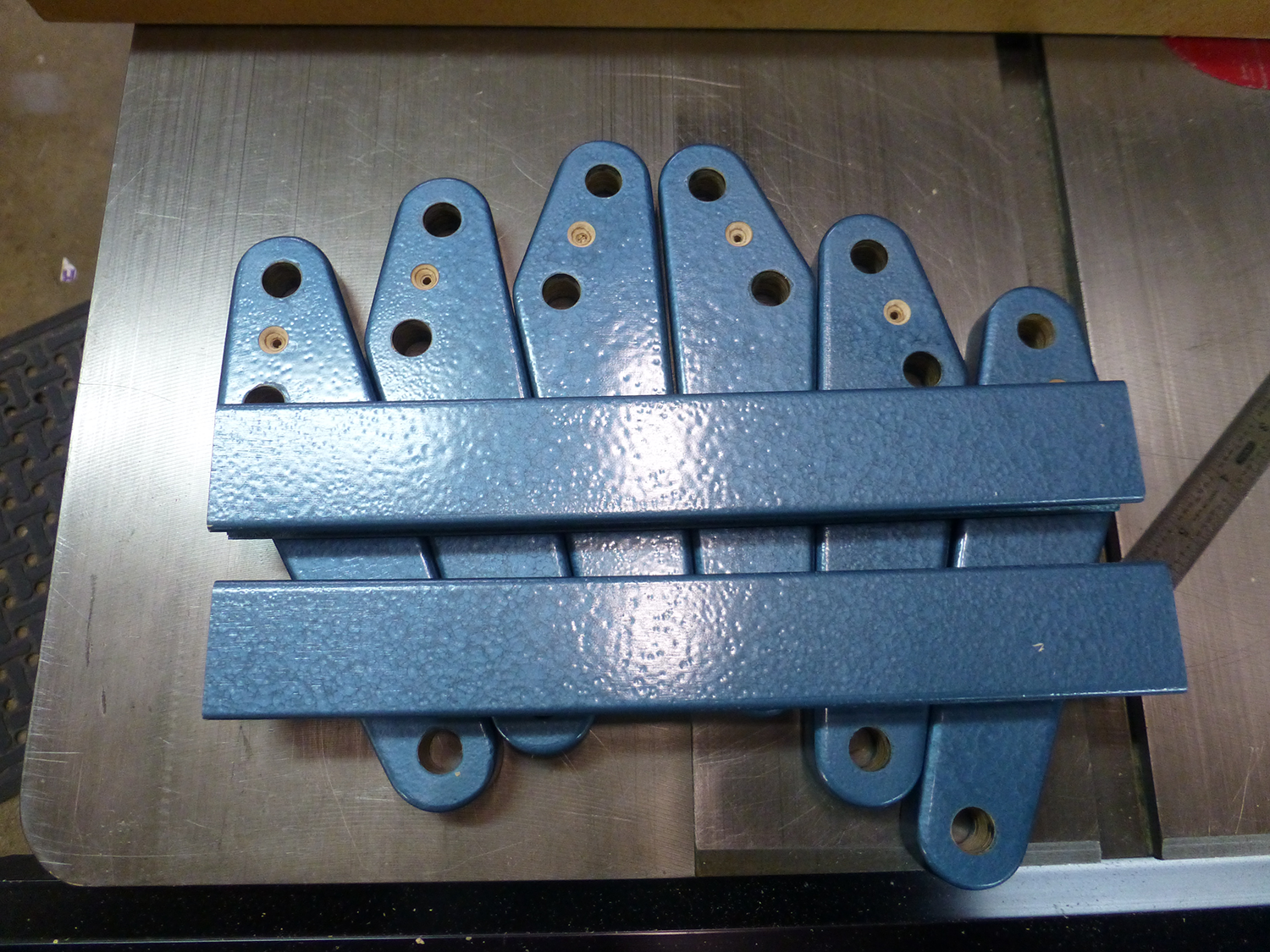
Here are the parts prior to assembly, and after starting to aseemble them. The steel rods were left long prior to final assembly, as I used my cordless drill to install them. They are a very tight fit, and nearly impossible to install if they are not spinning.
Two bottom rails connect the links, and support the bottom plate that the screw and nut mount to. Like the spacers, the bottom plate fits between the rods.
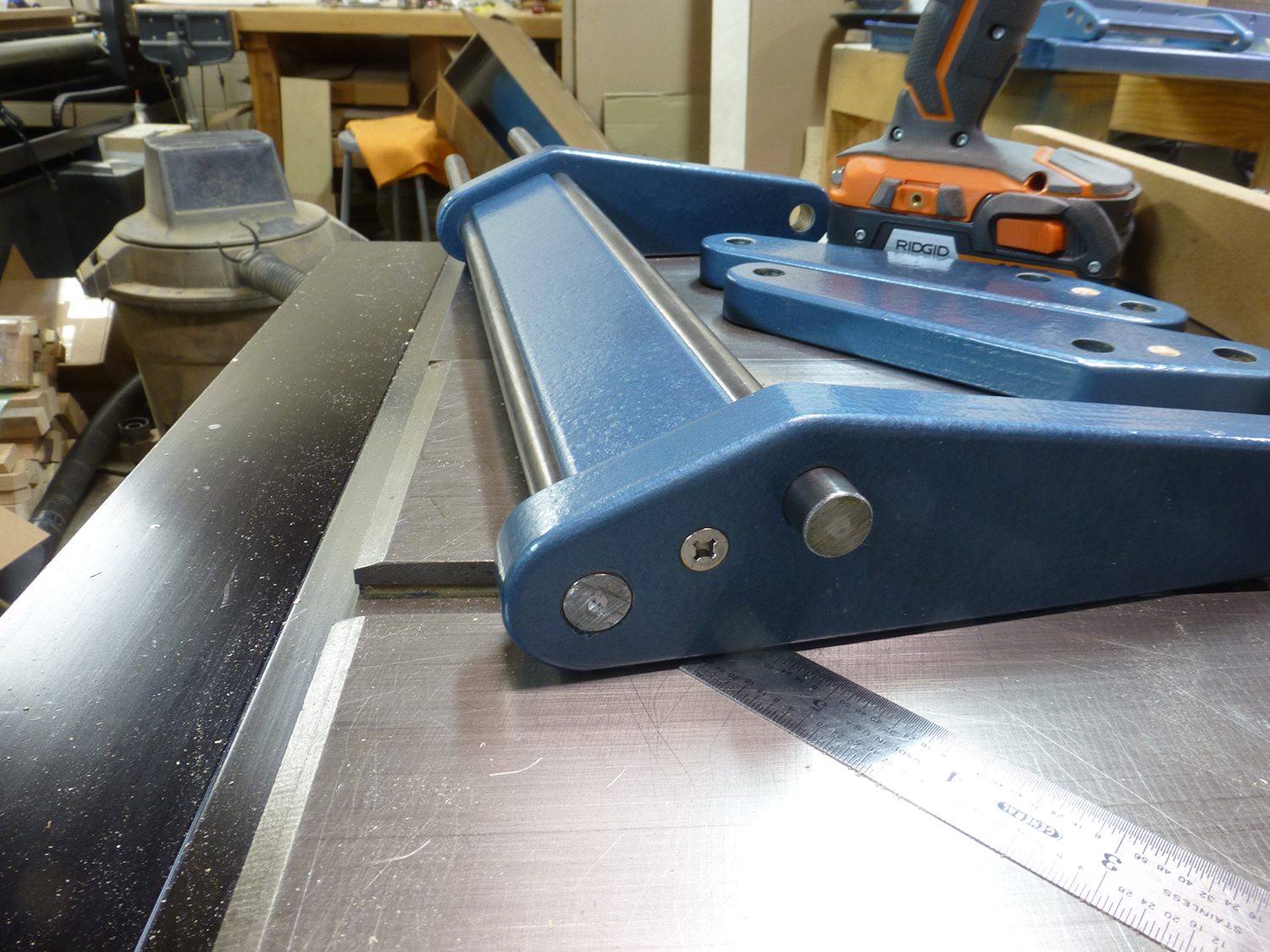
I used nylon washer between all moving parts, mainly to keep the paint from wearing off over time. Here's the links and bottom rails assembled and ready for installation. (Note: The links are backwards in this pic.)

With the mounting rails attached, the assembly is ready to be installed into the frame. (After it's taken apart and the links turned around)
For the table lifting screw, I borrowed some ideas from my CNC router.
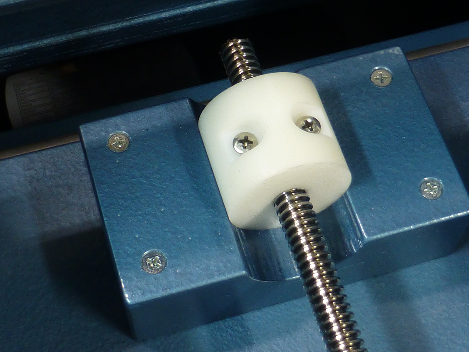
The screw is 1/2-8 acme, with a homemade delrin nut. This gives you a tight fitting nut, with no play. And delrin is slippery, so no lubrication is required.
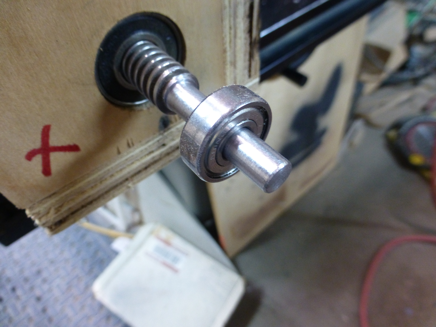
The screw is mounted in two skate bearings, which required turning the end down to 8mm. I don't own a metal lathe, but have a DIY solution. I have a box with a 1/2" bearing at each end to support the screw. I clamp the box to my table, feed the screw through it, and chuck the screw into a 1/2" drill. With the screw spinning, I use an angle grinder to rough out the shape, and a file to finish it upTo support the screw, I made a bearing block from 2 layers of 1/2" phenolic plate. I used a carbide tipped 22mm boring bit to drill the bearing pockets, then epoxied them together using an 8mm bolt through the bearings as a clamp.
After the epoxy cured, I trimmed the block to final size. I added a chamfer at the router table, and drilled and countersunk the mounting holes. I used t-nuts to mount the block in the frame.
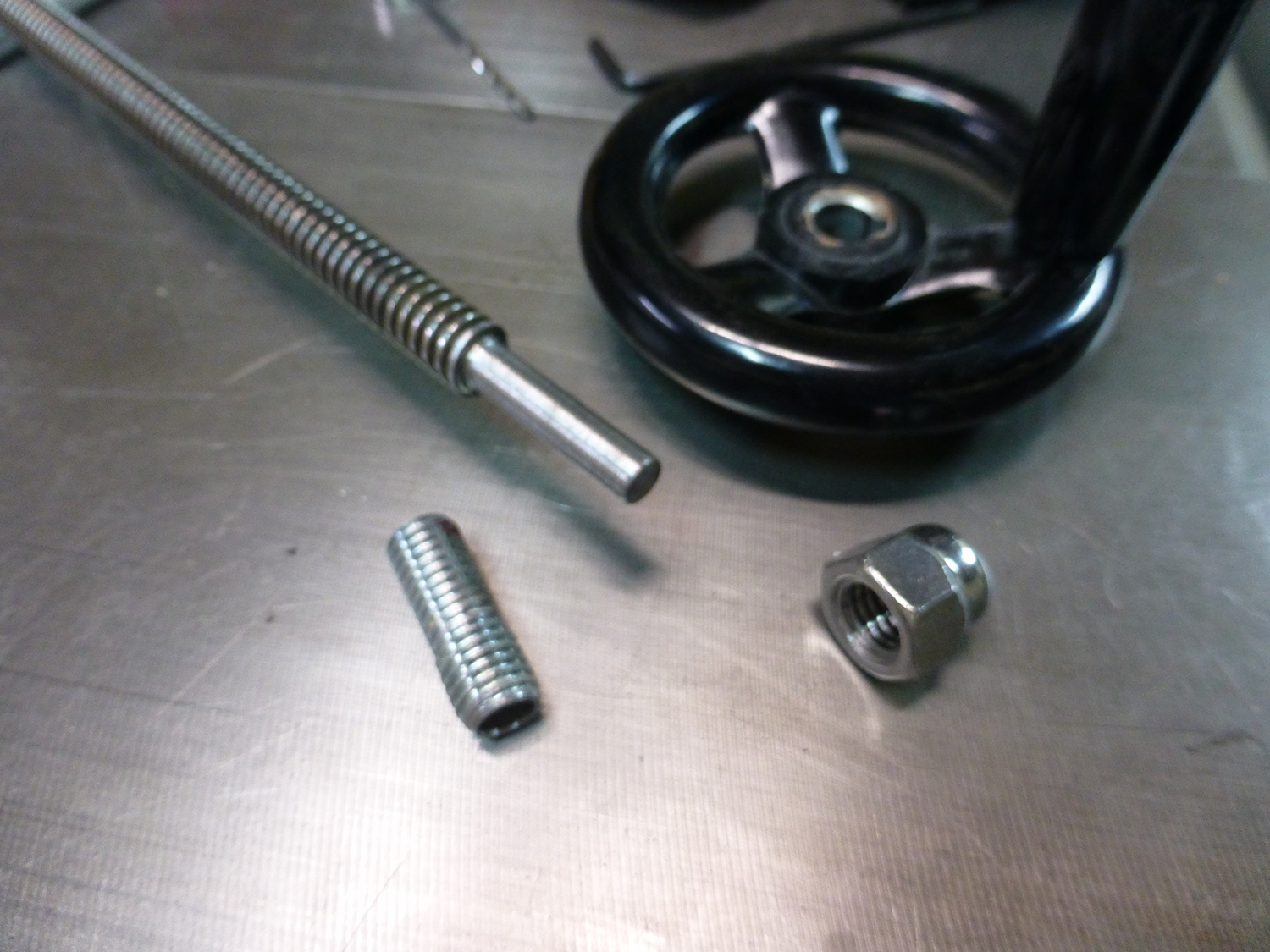
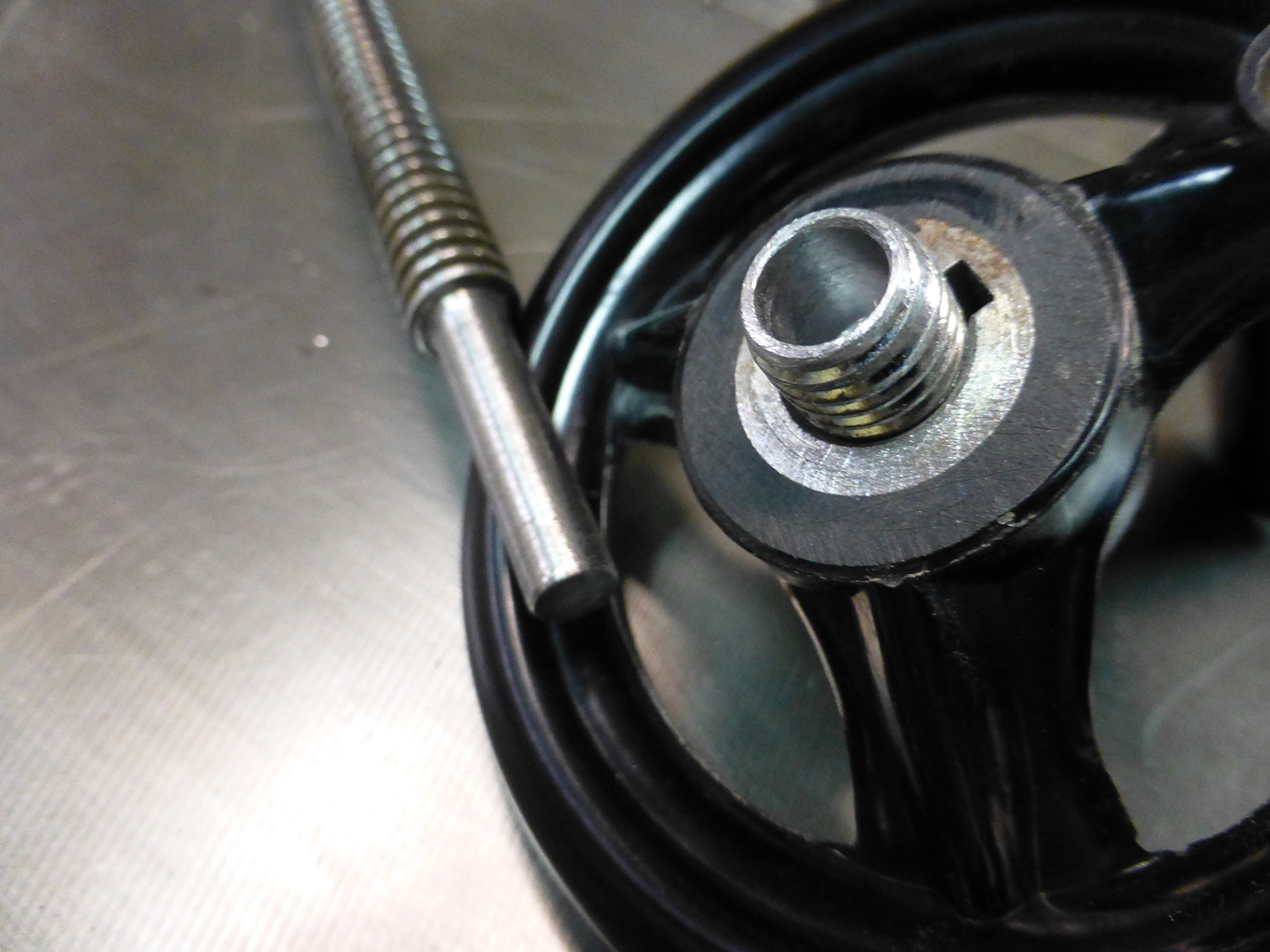
Rather than make my own crude handwheel, I picked one up for $5 from China via Ebay. It had a 12mm bore, and I now had an 8mm shaft I need to mount it to.
To make an adapter, I started with a cutoff section from a 1/2" carriage bolt. I chucked it in my wood lathe, and filed the threads down a little until the handwheel fit. This still left plenty of threads for a nut. I used a 1/2" stainless steel acorn nut. I then drilled a 5/16 hole into the end of the 1/2" bolt. I then slid the threaded rod into the bearing block, and epoxied the adapter on the outer end. I used tape as a clamp to hold it all together while curing. It's a permanent installation, but can be removed with a torch if needed. Epoxy breaks down at about 250°.
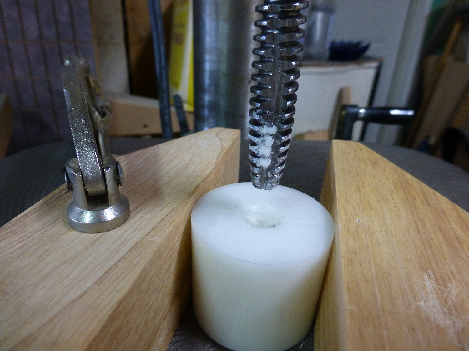
To make the nut, I cut a length of 1-3/4" diameter delrin rod, and drilled a 3/8" hole in the drill press. I made a tap from a cutoff piece of the acme rod. I chucked it in my drill and tpaered the end agaiunst my 12" disc sander, then cut a "flute" with an angle grinder.
I chucked the tap in the drill press, and turned it by hand. This was very hard work, and took about 30 minutes.
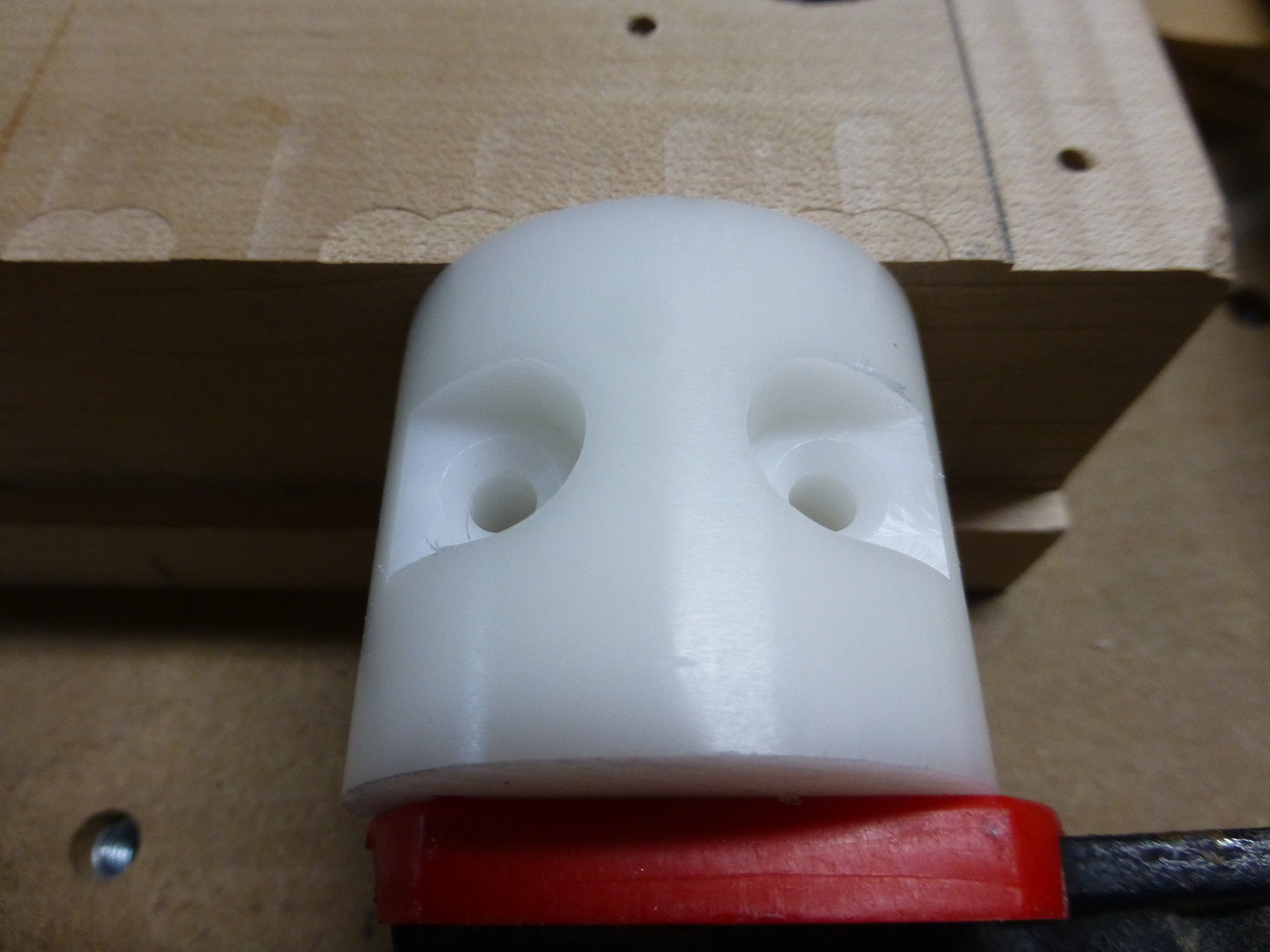
I then clamped the nut to my CNC table, and routed two recessed and drilled for mounting holes.
I glued up a mounting block from two layers of baltic birch, and CNC routered the curved recess for the nut. Two t-nuts on the back of the block accept the nut mounting screws. Here's a pic of the parallelogram installed. The top rails each have six t-nuts in the undereside, which allows bolting the infeed table down from the top side.
Belt Guard.
The belt guard frame is two layers of 3/4" MDF, with a face of 1/4" MDF. All parts were CNC cut, with the mounting holes drilled as well, to align with the t-nut holes that were done when the front base panel was on the CNC. All surfaces were sealed with epoxy prior to painting.
Assembly.
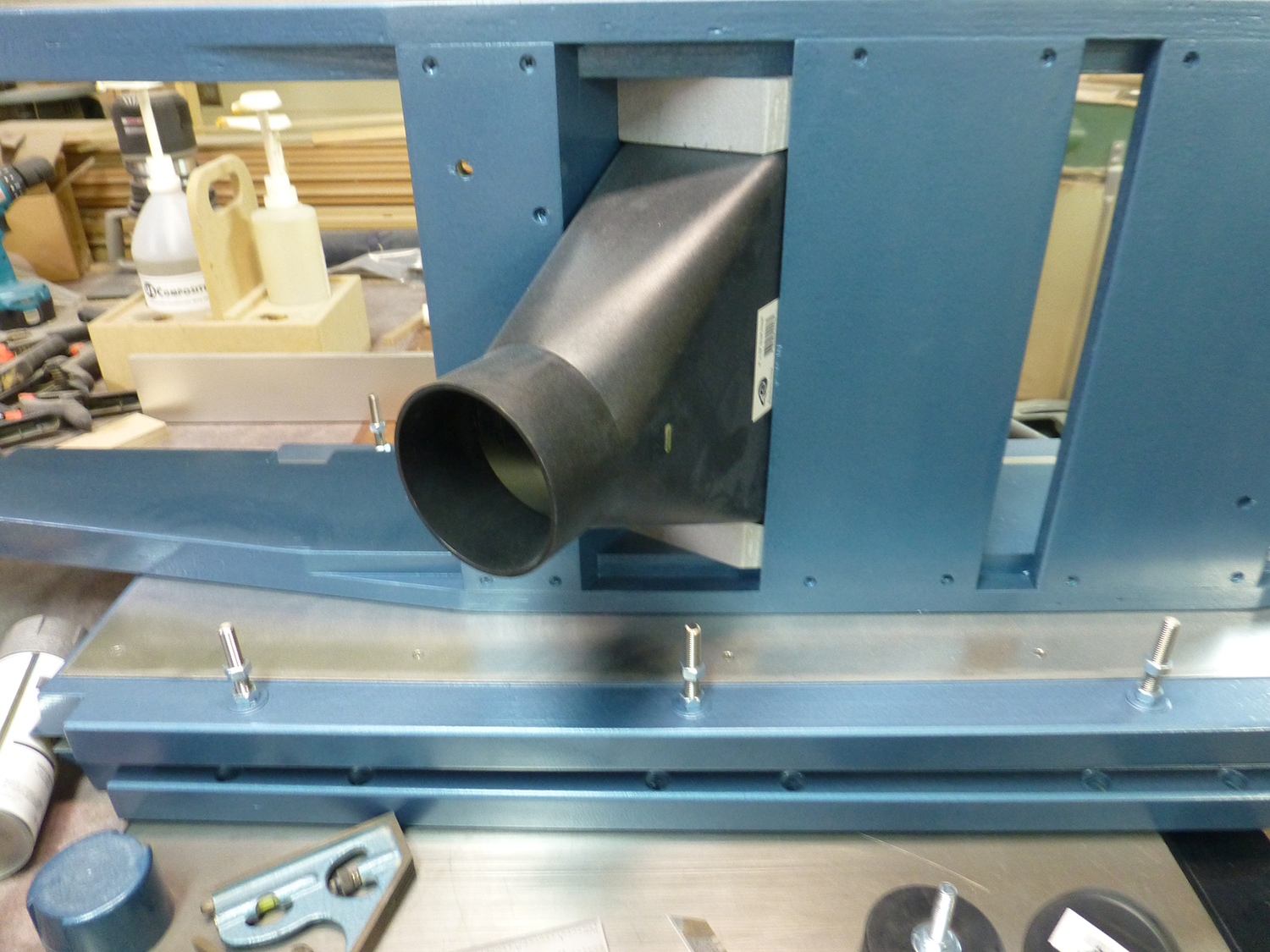
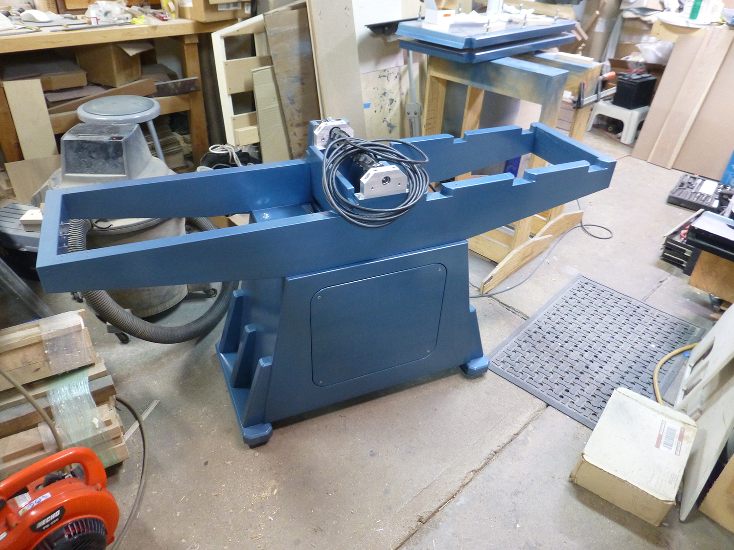
With everything painted, I could start on the final assembly. The dust chute is held in with a few dabs of silicone, and is a very tight fit, as I built the frame rails around it. Since it's narrower than the frame, there are two small blocks, one on either side, to close the gaps, and lock the chute in place. With the chute installed, I could mount the frame to the base.
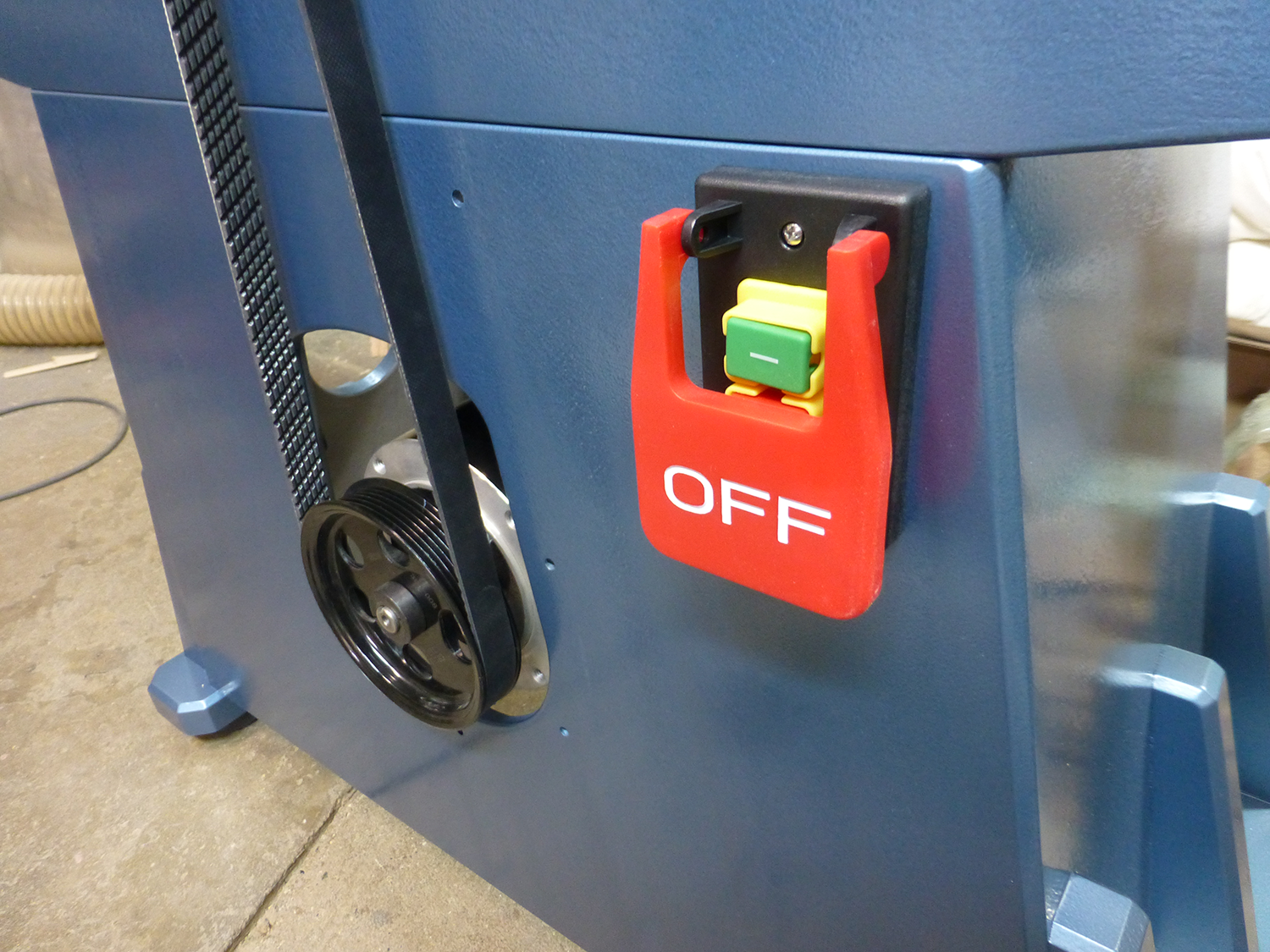
I picked up a 220V switch from Amazon. With the 2HP motor running on 220V, this thing gets up to full speed immediately.
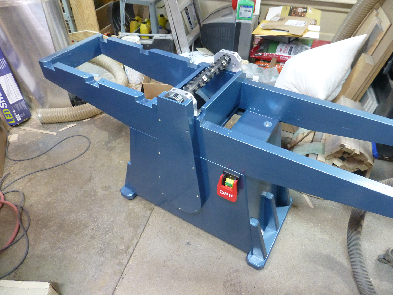
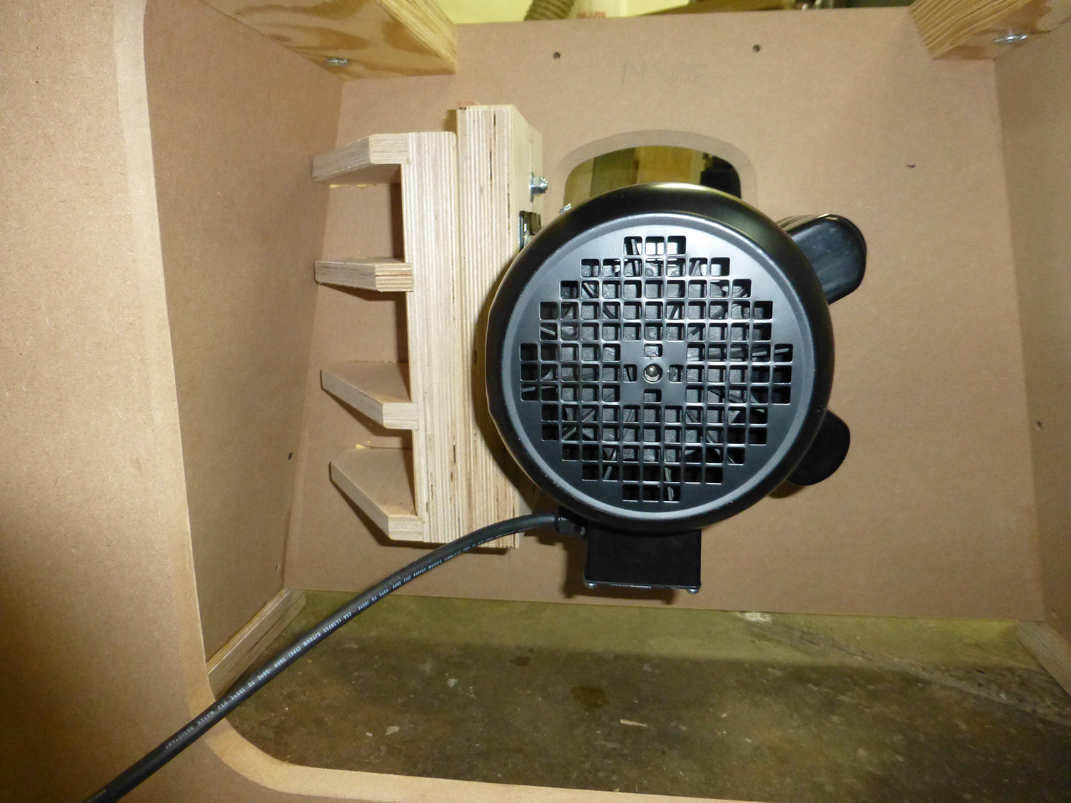
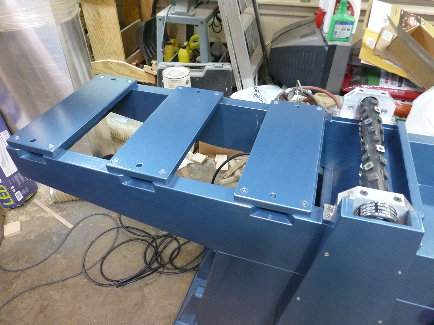
Here's a view of the cutterhead with a view of the dust chute below. This configuration works very well. Rear view of the machine showing the access door for the motor. The dust hose is also attached behind the access door. I keep a 10ft length of hose permanently attached to the machine, and can roll the dust collector over to it.
Once the frame was in place, I added the mounting rails for the outfeed table, and then set the outfeed table in place.
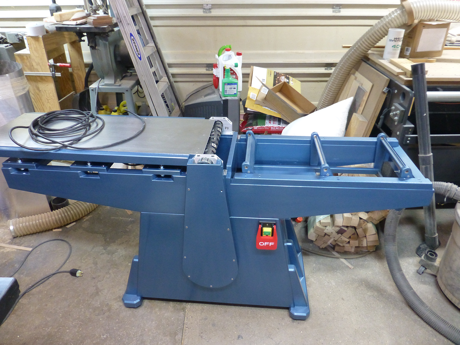
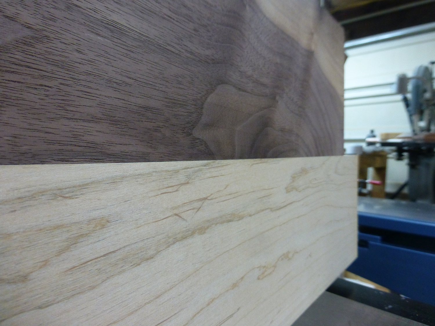
The last thing left to do was to bolt on the infeed table I had to shim it to get it flat and parallel with the cutterhead. I then set the infeed table height even with the cutterhead, and adjusted the outfeed table to match. Here's a picture of the first two boards I ran through, showing the jointed faces, and the jointed edges together. I didn't spend a lot of time adjusting the tables, but the first results are very impressive. I'll probably need to make some minor adjustments after it sits for a bit, and I'll get some longer boards to check the tables after I get the fence built.
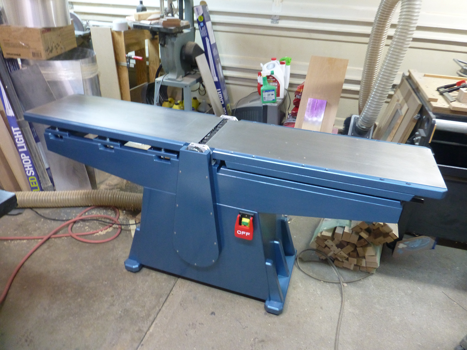
Here's a video of the first cuts on the fully assembled machine.